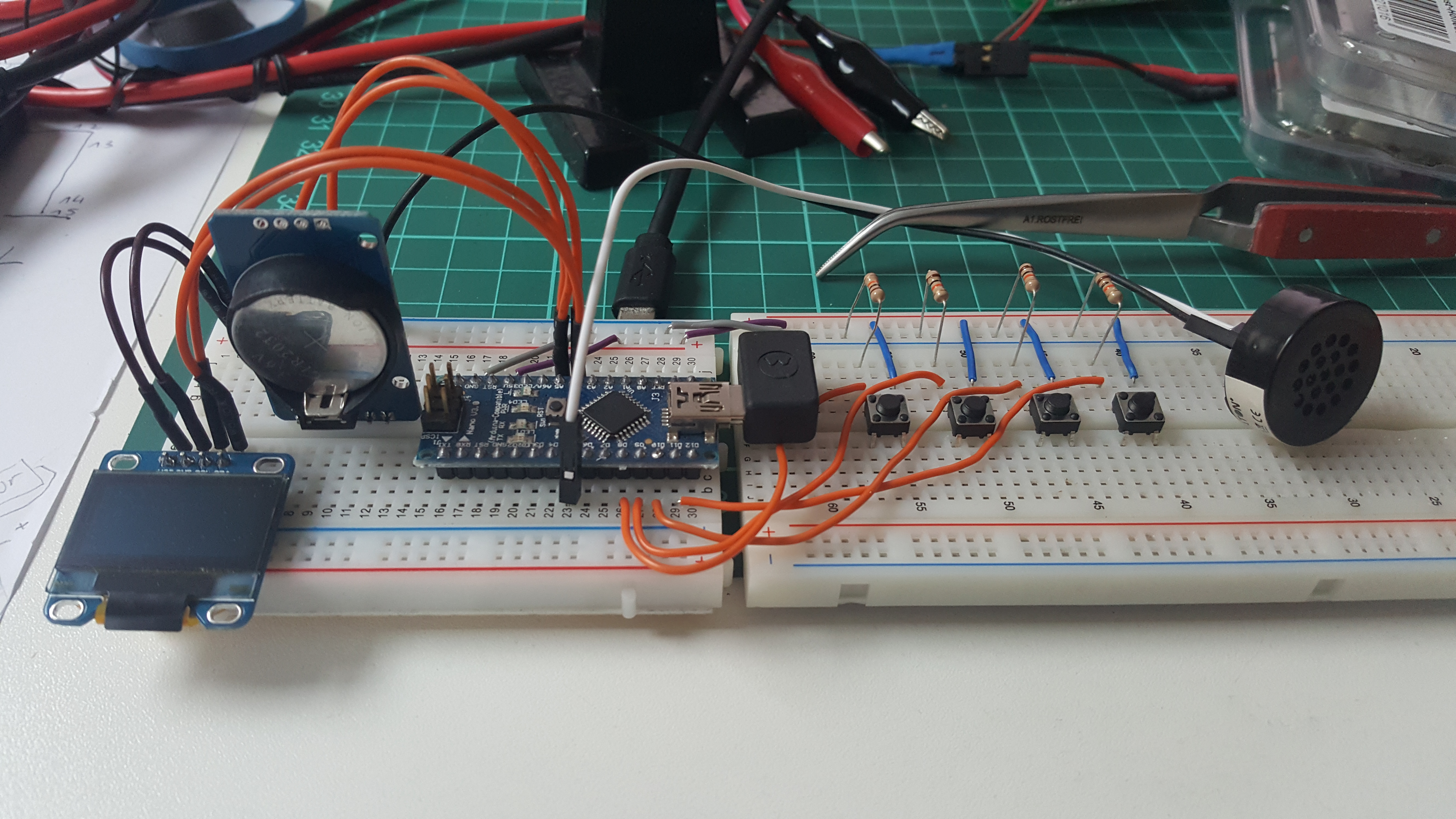
The design principle of keeping everything to a minimum is also paramount in the Tamagotchi project. In this case, I wanted to use the Arduino chip itself and layout a board around it by myself and luckily, I also found out that my slaughtered external phone battery delivered 5.1 Volts which is in the operating range of the Arudino.
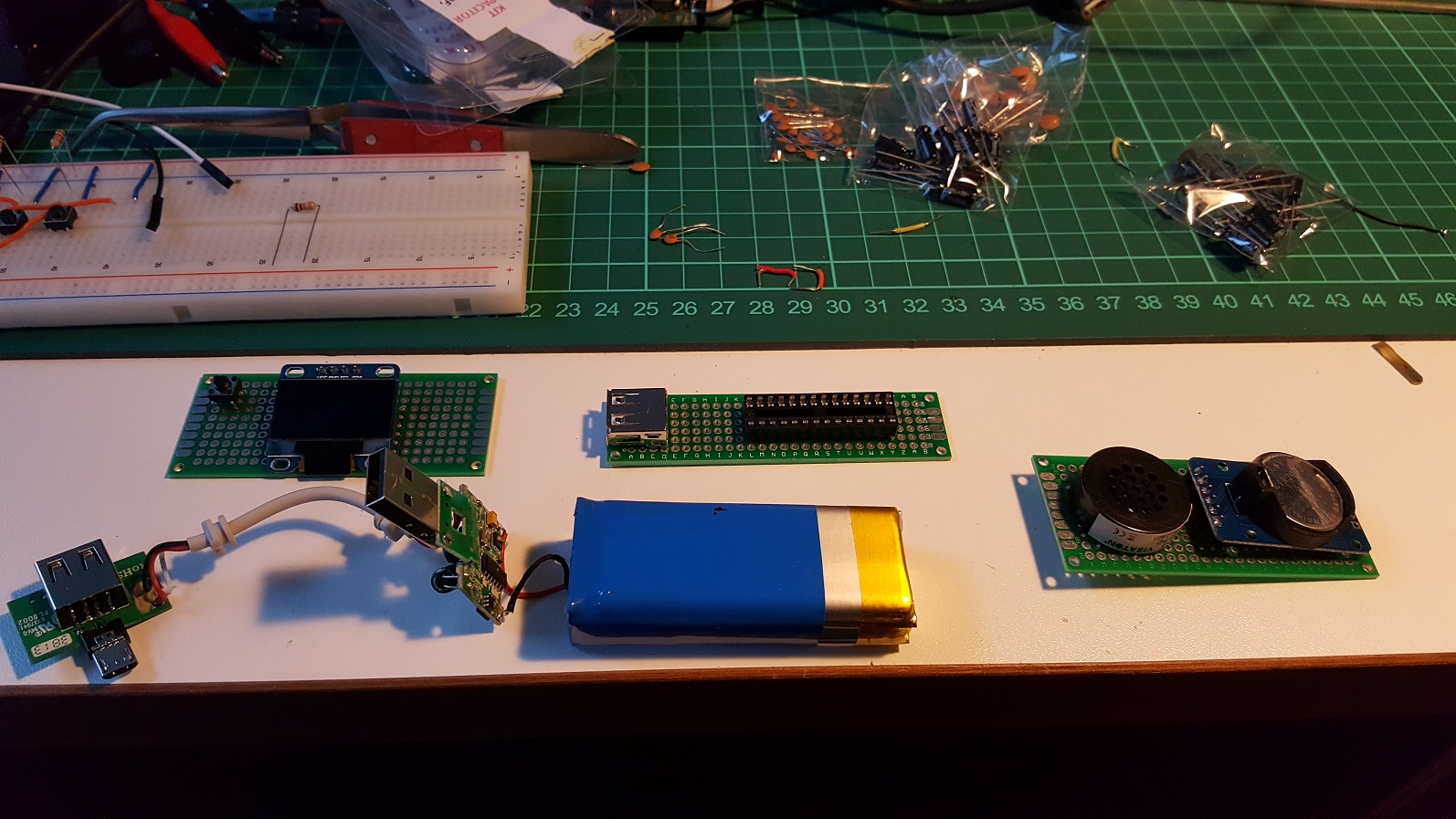
Tamagotchi PCBs
Top left, you see the front board with the display and the intended buttons (only one placed), top middle the board for the Arduino and it socket plus an USB port that will be used for the LiPo charger board (the one that is close to the battery) and on the right it’s the back plate containing the speaker and the RTC board.
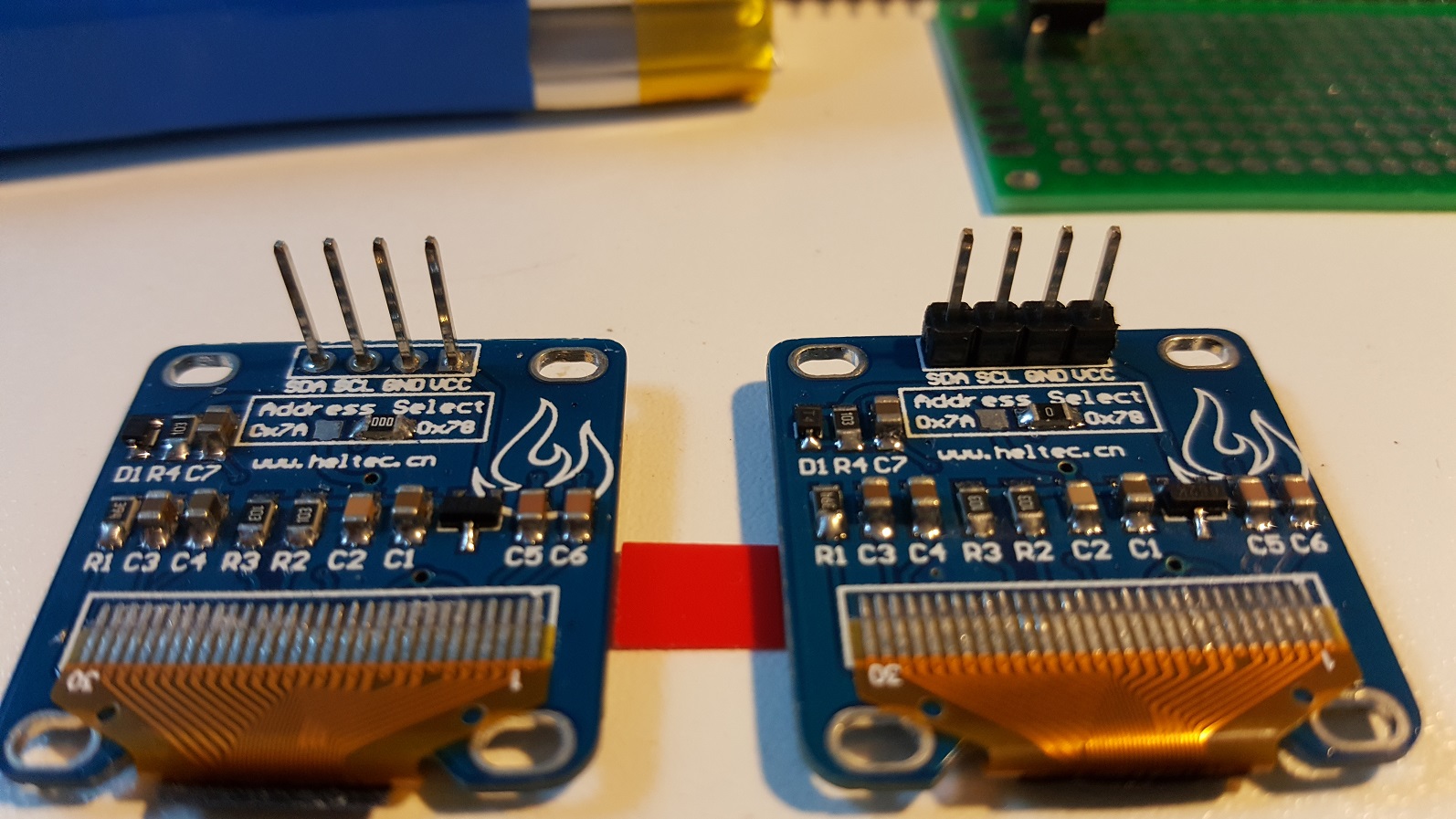
Display distance holder removed
Since I wanted to keep the volume of the device really low and everything tight, I decided to remove the distance plastic between the pins. I also taped the PCB of the OLED screen so that it could touch the perf board without the danger of shorting anything.
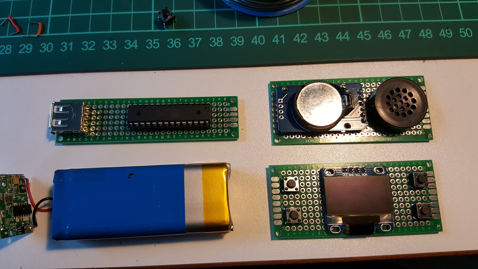
soldered boards without wiring
So that’s all boards with the bigger parts soldered, there’s the wiring missing as well as the quarz and some resistors etc, but for getting a feeling about the size of the final design that was good enough.
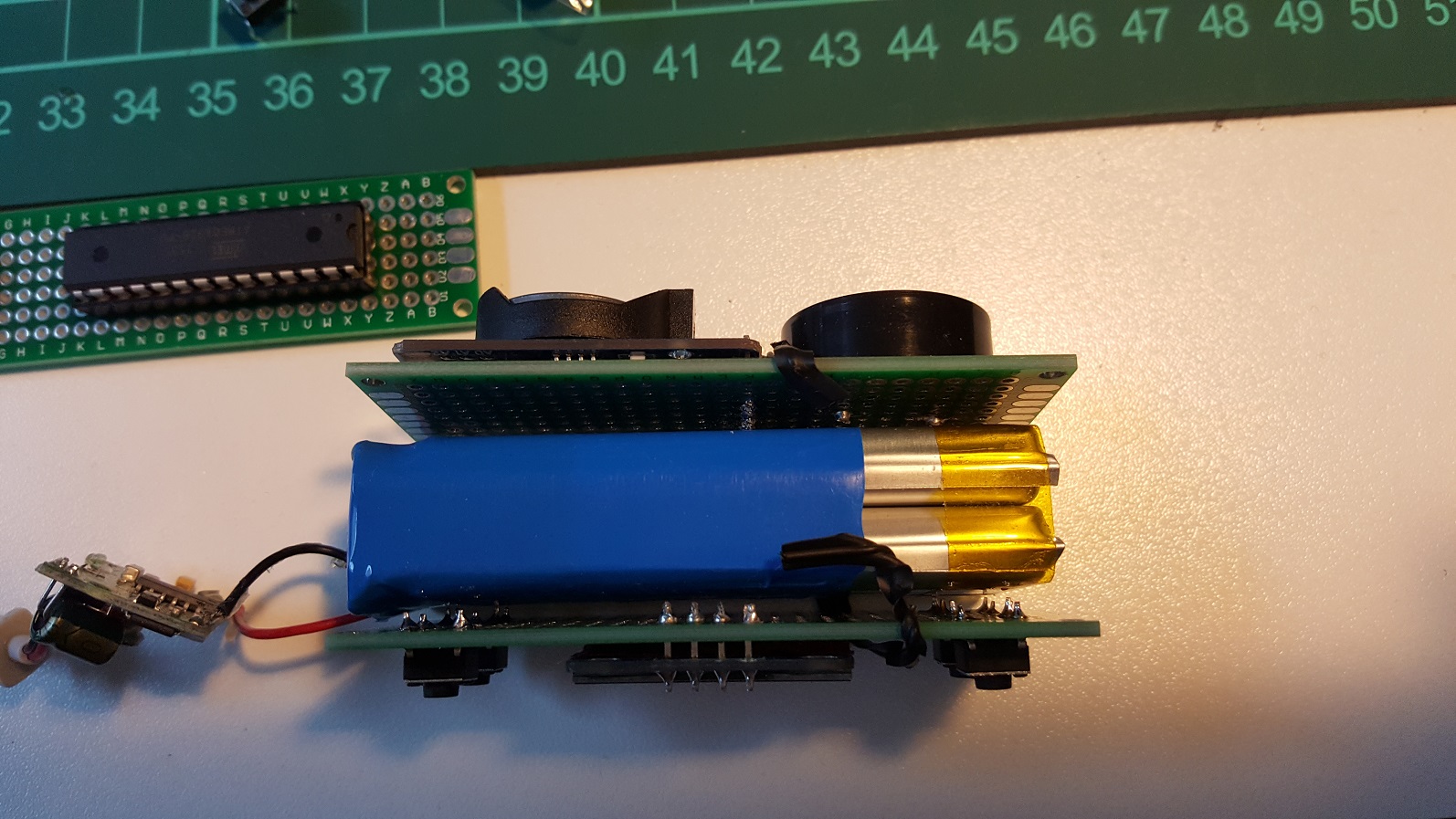
Front and back board next to battery
I also cut the long pins of the speaker, RTC and OLED after soldering them as short as possible. I’ll also add some thin mouse pad plastic between the boards and the LiPo on final assembly to prevent the pins scratching the battery.
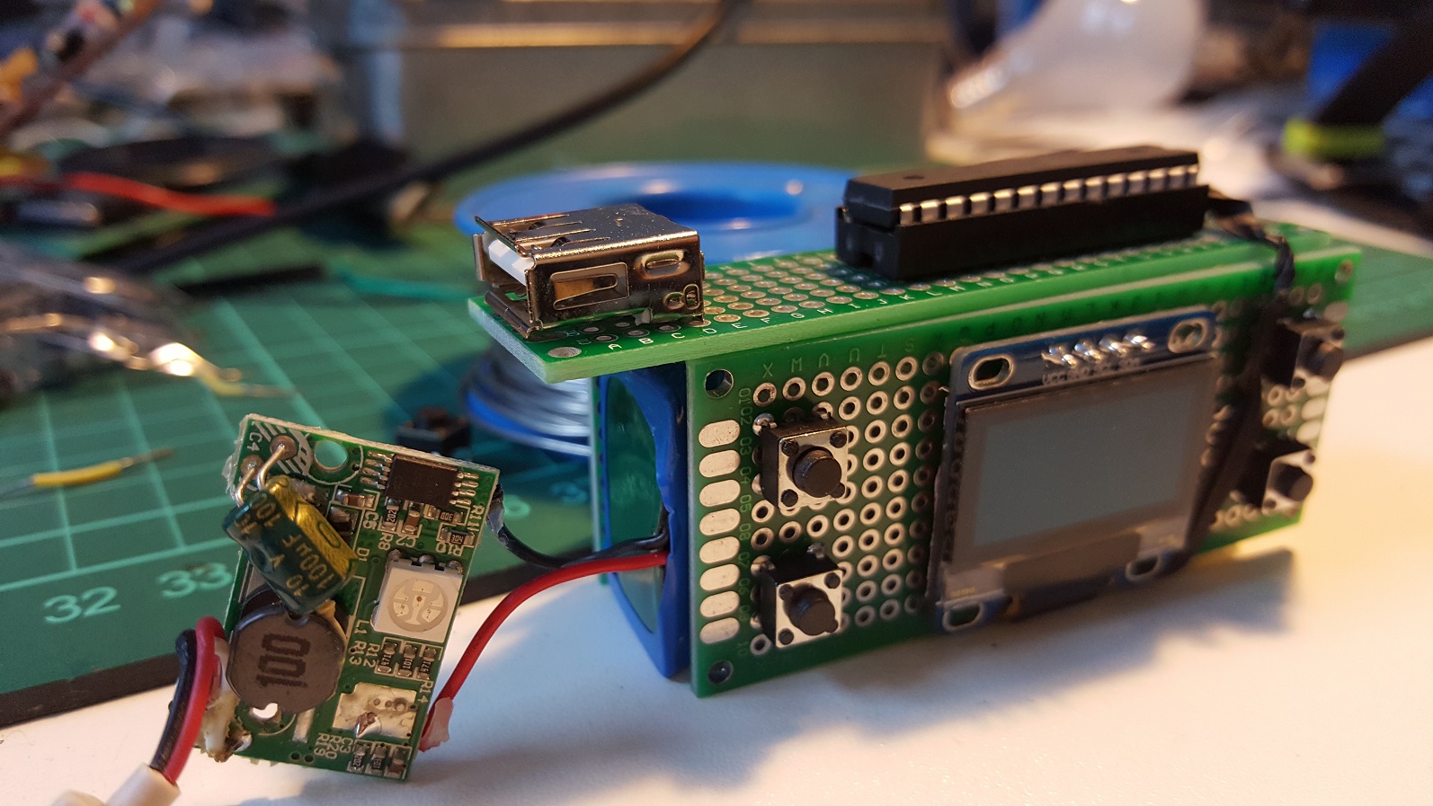
Arduino board added
I was also pondering about putting the Arduino on the back of the OLED board to save height but actually, I think that the Arduino as a core part of the system somehow deserves a prime spot on the device. I’ll place the FTDI header pins between the USB port and the socket so that I can easily reprogram the chip.
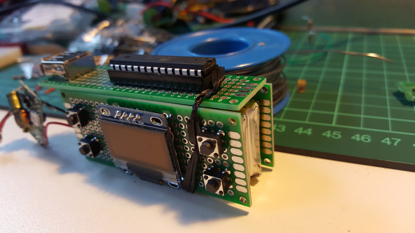
Arduino Tamagotchi from the left
So that charger board will go to the left and connect to the Arduino board’s USB which wil “close” this side.
I plan to connect all boards with blank wires (that’s why there is a line of holes above the buttons) so that I can easily wrap the “multi-part motherboard” around the energy source.