so, after i’ve connected the head and its servos to trashbot 6, it’s now time to work on the actual control of the neck servos. unfortunately, the servo-board connected to the raspberry is not sufficient to control the neck servos since the body is already using 15 servos and the controller only has space for 16.
so i thought to use an arduino mini pro for this since it has 6 PWM outputs that can control six servos (people have noted that the output pin doesn’t necessarily have to be capable of PWM to control a servo).
also, i thought i may do some kind of power managment in the future with the arduino in that it may be connected to a PIR and boots up the pi upon detection of a movement.
so with these considerations i chose the arduino mini pro instead of my beloved arduino nanos since it is smaller and uses less power since it spares the usb controller. this in turn has another advantage since my usb ports in the raspberry are rare anyways.
this means that i also need to connect the pi through its serial port via the gpio and ideally also install arduino ide on the pi to actually be able to programm the arduino from the pi, i.e. not connect the arduino using a usb cable to a pc as i’ve done in the past. that would be really, really elegant.
to learn all this, i plan to start small. first i soldered the pins to the arduino and also made sure that the DTR pin (also called GRN), which is positioned on the side of the arduino is also in line with the other pins.

courtesy of http://weworkweplay.com/play/connect-jy-mcu-usb-serial-port-adapter-to-arduino-mini-pro-3.3v-atmega328/
this will have the advantage to use one straight socket for the arduino instead of an additional for the side pins (that are intended for FTDI) and i can also use it on a breadboard:
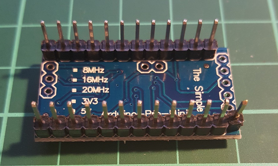
DTR pin of the arduino mini pro
next, i connected the mini pro to an FTDI to test it with my PC based arduino IDE. since i seem to have a chinese version of the arduino, the pins are a bit different from the regular pinout. but anyway:
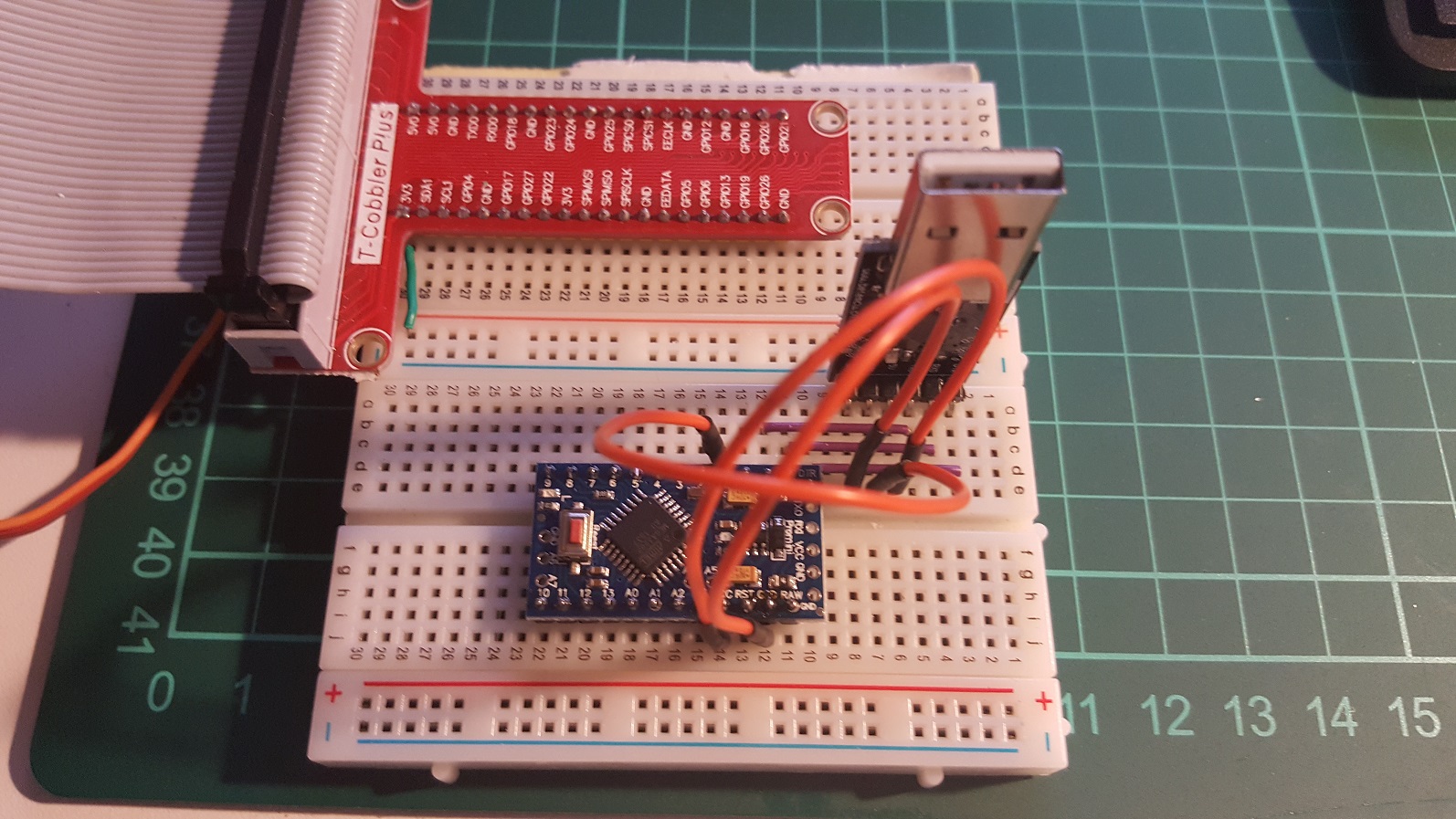
arduino mini pro connected to ftdi
next i uploaded the “hello world” blink code and the IDE didn’t find the arduino. so i checked the connections and actually found out that the lower GND pin was not working, the soldering was not good. re-heated and then it worked!
so, do hardware unit-tests before you build more complex stuff. next stop will be to add some equivalents of the neck servos and check the pwm pins, if that works then i can start connecting the pi to the arduino and try to find out whether i can program it from there.
EDIT: after i posted this article on reddit, people mentioned that the DTR pin is actually the same as the RST pin and so my mod wouldn’t be necessary. but then other people actually noted that they are not the same. in the schematic you see a capacitor between DTR and the chip’s RST. i can’t judge whether this is the same as RST or not… i just want to be sure that i can program this thing like using FTDI.