(if you can’t wait to see the end result, scroll down to the bottom watch the second last video 😉 )
after the lower body was walking and free from seizures when starting up the arduino, it was time to think about the rest of the robot. certainly, there’s still much to improve on the gait and most importantly the feet, but it’s my goal to build up the complete robot first before iterating the parts (the feet are under constant change as the weight distribution varies and also i’m constantly learning how to improve gait pattern.)
in contrast to many commercially available robots (like the bioloid or the lynxmotion pete), i wanted to have a machine that feels more natural and can move a bit more freely, especially with the head and the body trunk. usually, these two are rather stiff or absent (head). people invest dozens of servos into legs but not a single one into the spine. for me, the two servo legs are “good enough” for the moment, i’ll invest in the rest first.
on the other hand i’ve seen many gimbal mechanics mostly for quadcopters carrying the camera. some of them were even arduino controlled and here and there, you can see some code. interestingly, i wasn’t really able to find servo-driven automatic gimbals, most of those are driven by dc motors.
let’s view the goal first:
okay, here’s how i built it:
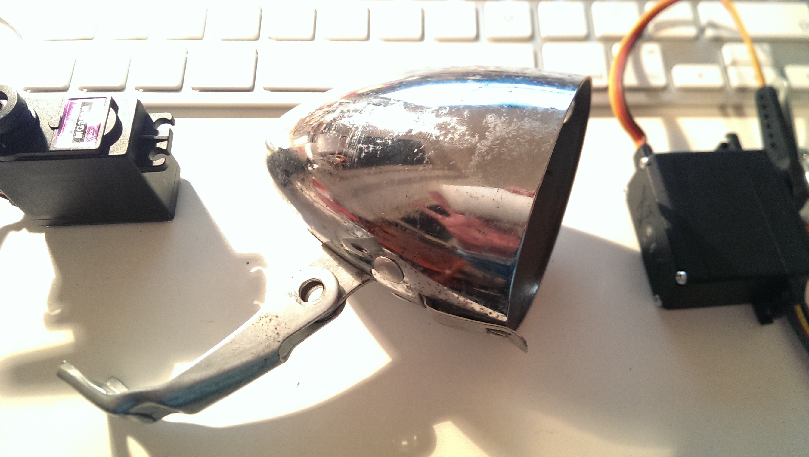
the base was taken from anold bike light:
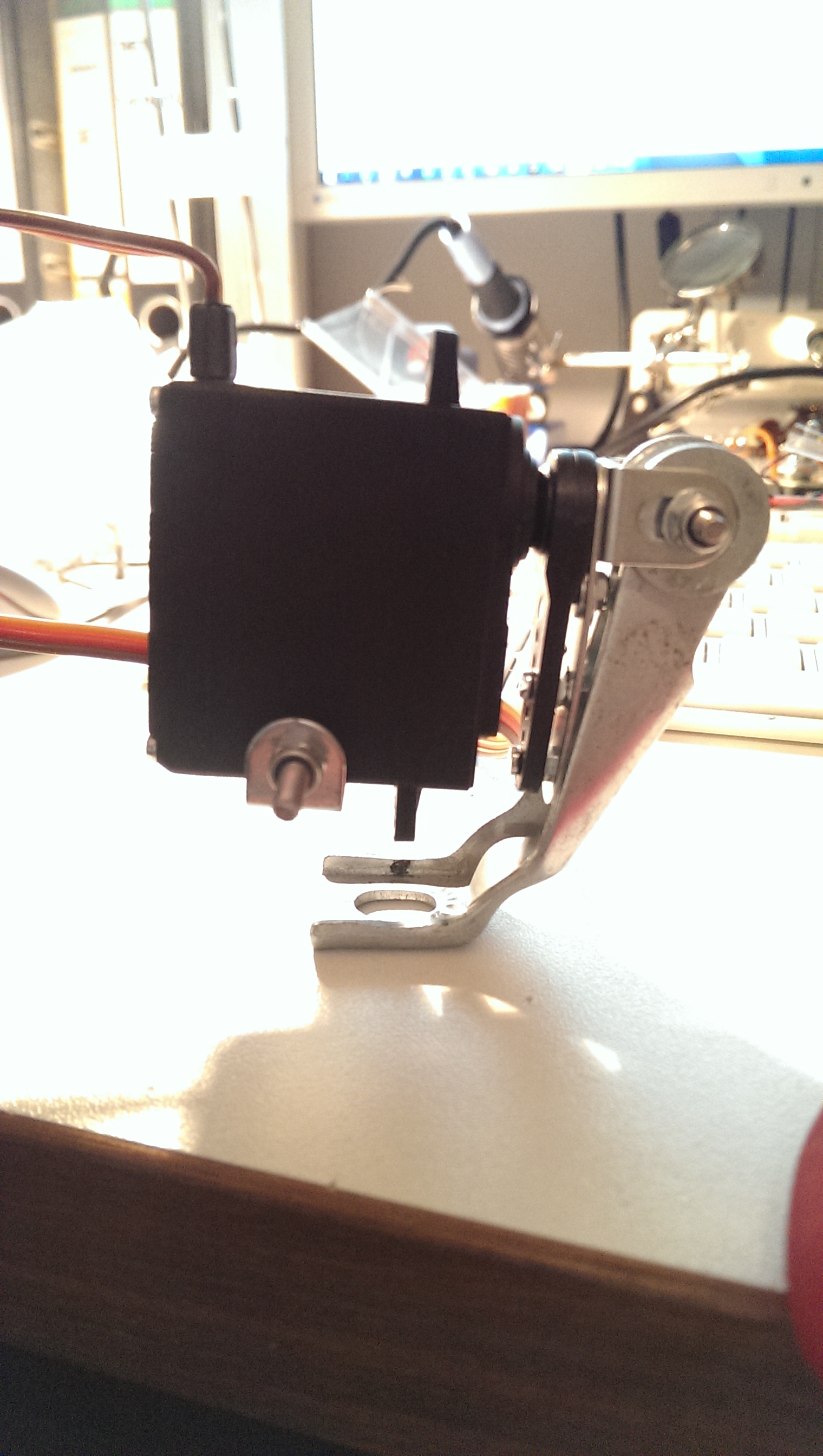
and i added the first servo that can swing from left to right:
next up, was the second servo driving the chest allowing the bot to lean forward. it seemed to me that these are the two directions the biped needs to be stabilised in, since the feed generate a tilt to the sides and the hips rotate body on that tilted axis.
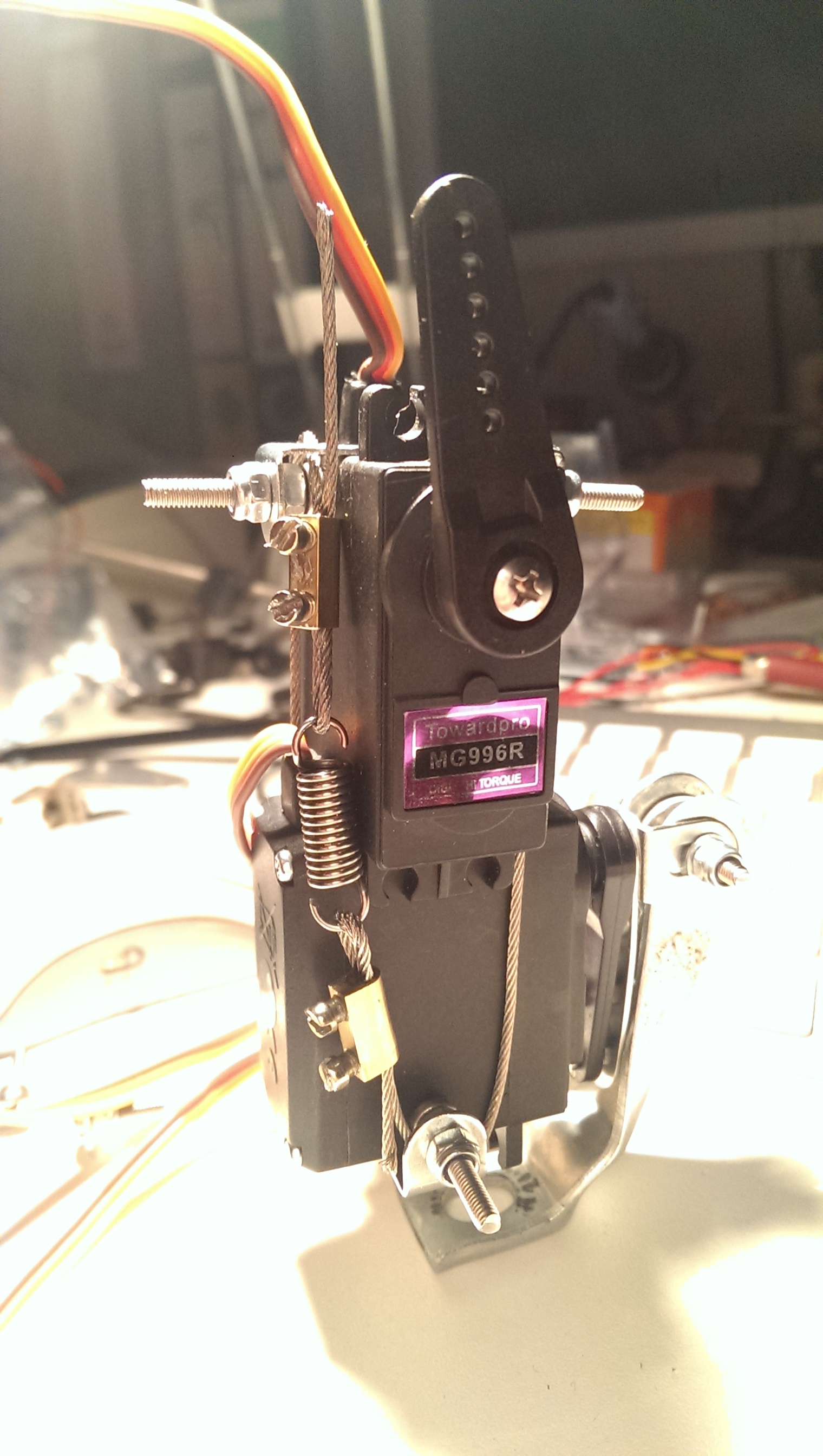
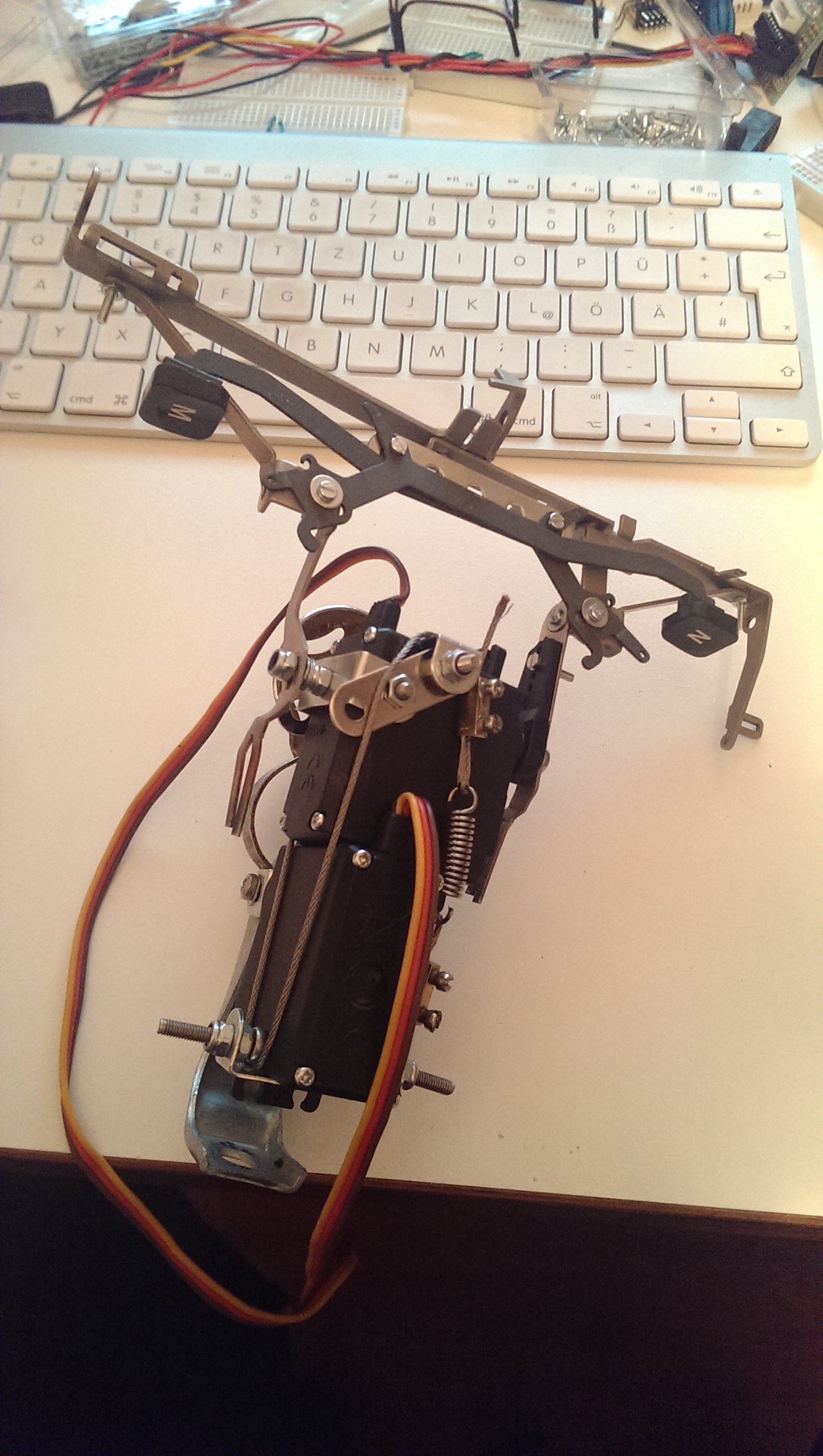
i wanted to have a possibility to update the mechanism easily and didn’t want to glue or solder anything, also bulky servo brackets seemed not the right way to go aesthetically. so i came up with a wire-based connection of the two made from a recycled wire that i had left from hanging lamps and some power connectors and a spring from the recycled typewriter:
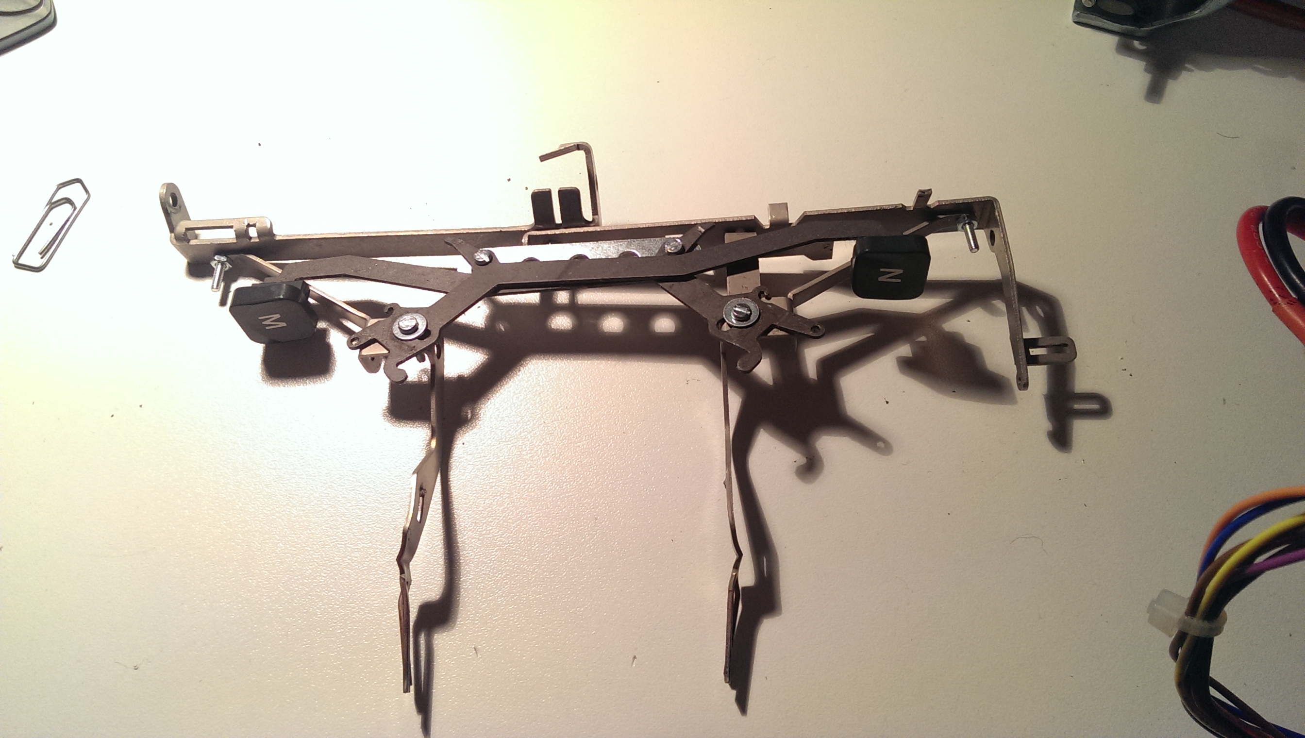
it took a while to find the right parts from the type writer and re-arrange them so that i had a broad enough shoulder that could work as a “servo bracket” while being stable enough to support more hardware on top later on. and i recycled my first two letters “M” and “N”:
finally, connecting the two parts to this:
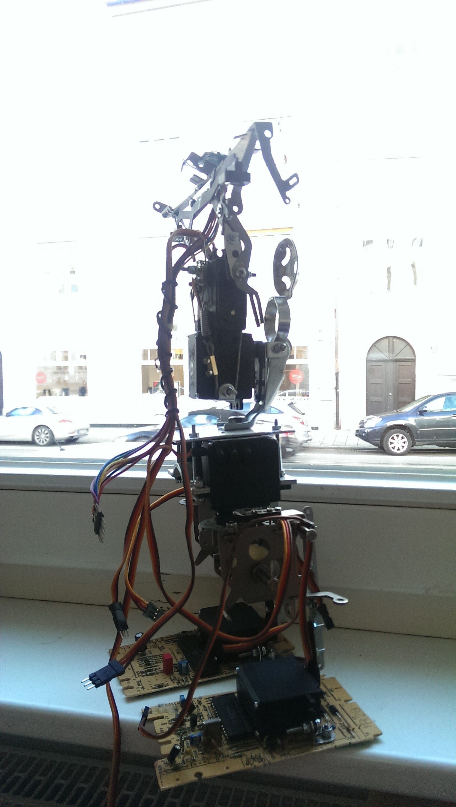
it was really tricky to find some parts to surround the upper servo so that i could atttach a second ankle on the other side of the servo. kind of proud to have it included in the wire fixation structure… also, you see a recycled air pump holder from an old bike that protects the bot’s chest servo should it fall backwards.
next i recycled a heat pipe from an old (TV?) pcb: 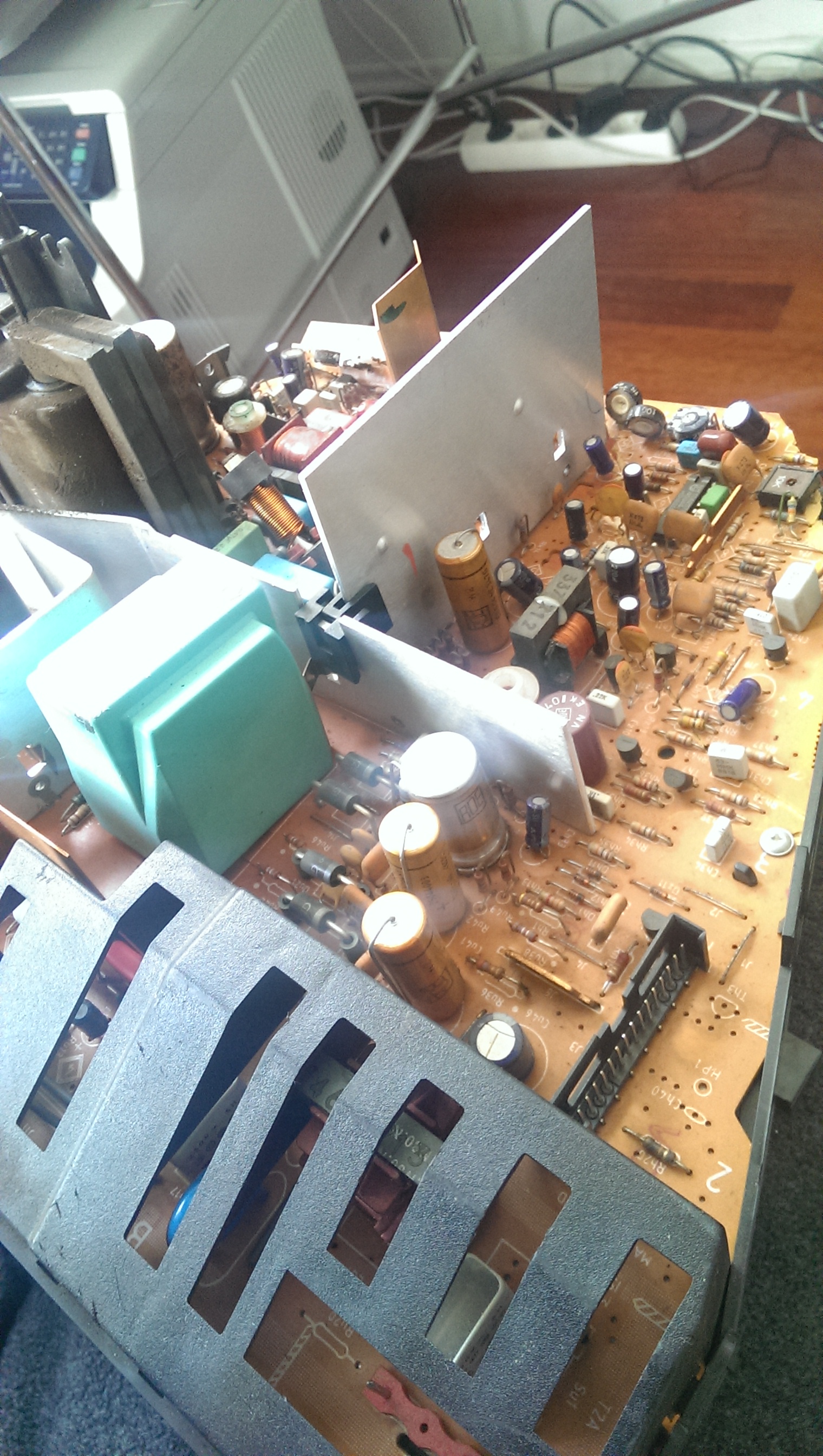
and shaped it to support the upper body on top of the hips and TADAA! here’s the assembled trashbot 3: 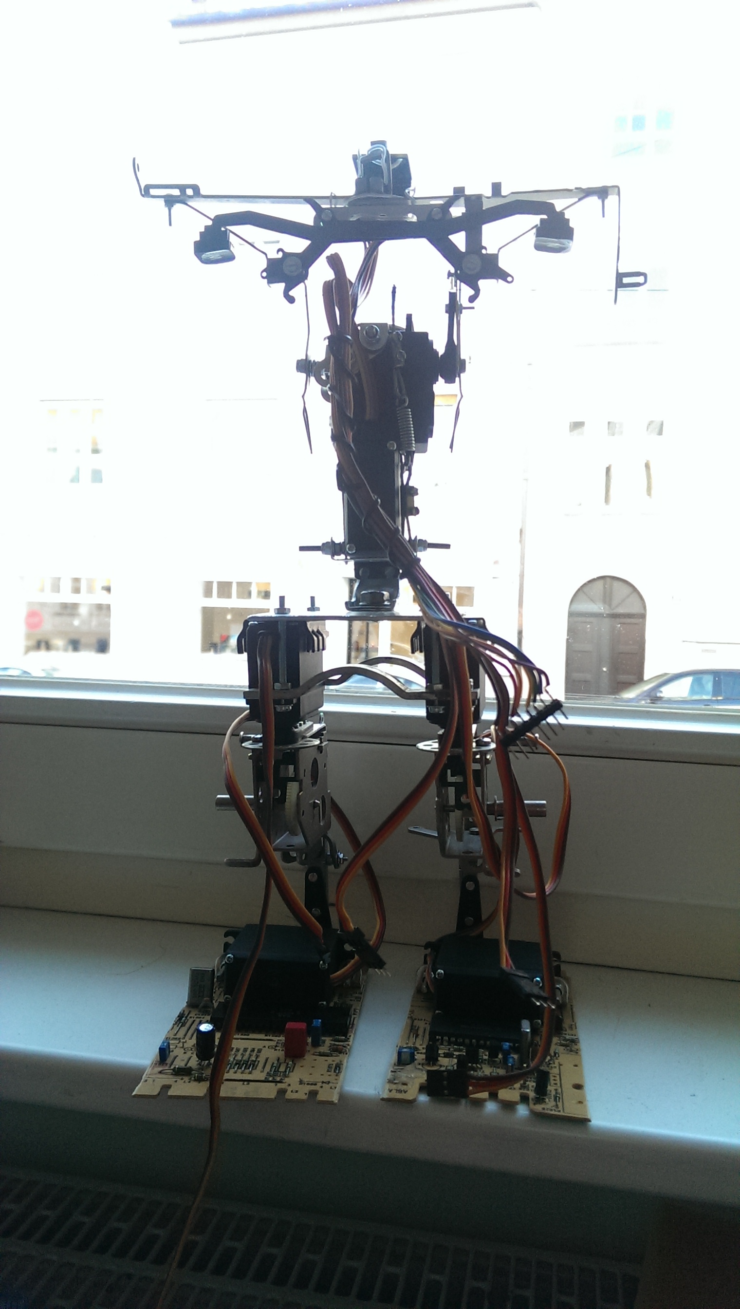
now it was time to develop the electronics and the software. (actually, i developed the software with the spine detached and assembled the whole beast when the autonomous gimbal was actually working).
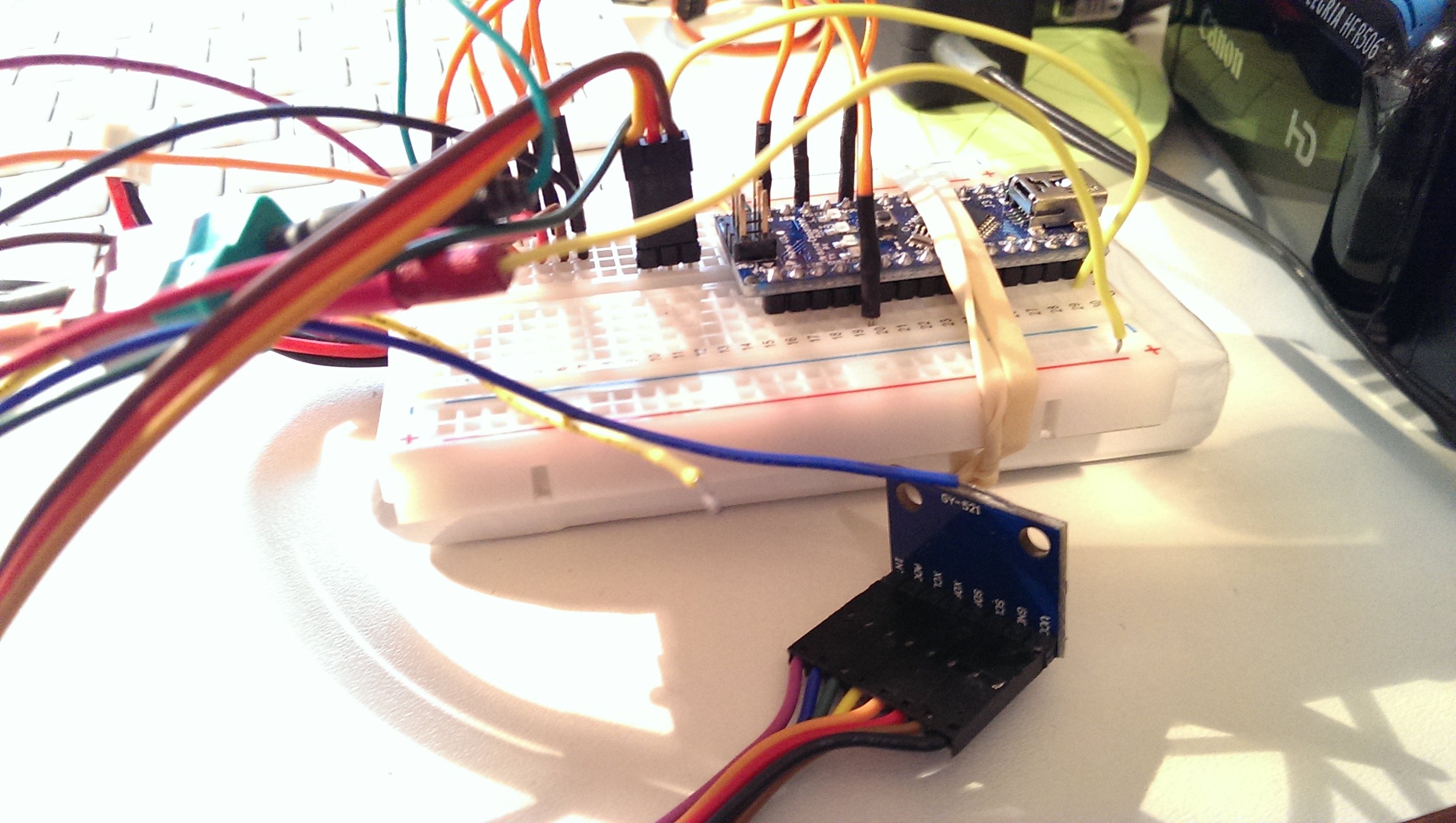
standard setup with the gyro / accel MPU6050, most importantly with the interrupt attached to the arduino:
i tried a could of libraries for getting decent values (including the kalman filtering that can be done on the DSP of the MPU itself), but jeff rowberg’s is simply the best.
finally i wrote my own PID functions, mostly to understand how the maths work and how and whether i can fine tune something. PIDs are beasts as they are designed to self balance to a set value. now if the actuator and the sensor are attached to each other and controlled via a PID the whole system can swing like HELL. actually i burnt my first servo playing with the setup and was happy to learn that my humble mechanic design worked really well for maintainability…
i used mostly these links to understand how it works:
- a video explaining PIDs and how to tune the parameters
- some discussion on PIDs and servos
and lots of reading around this. the problem is that nobody can tell you how to tune your PID in your setup. so there’s a whole lot of trial and error with many strategies being published on how to find the right parameters. as you can see in the video, the parameters are sort of okay, but still the system is behaving a bit “choppy”. but if i react too often to the sensor values, the system starts to swing. so here’s some homework left and i hope that this blog post will spur some discussion in the forums. and there’s a nice blog post that obviously led to the PID library included in the arduino software distribution. i also want to learn from that.
let’s see the system in action:
finally, i also studied a bit how the bot walks with and without the gimbal active. the first part of the video shows it from front and top with the gimbal active, the second part shows it from top and side with a stiff upper body.
you can see that the upper body’s lateral amplitude is higher when switched off. this will be even more the case when we load the shoulders with a head and arms in the next iterations.
i will do another blog post investigating the gimbal effect more deeply. i just bough a tiny camera that i can attach to the neck and will tape trashbot from “first person perspective” 🙂
