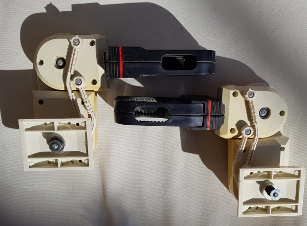
I always wanted the Omnibot to be able to actually grab and lift objects. So I started with the arms and recycled the 2 DoF shoulder servo pack from Trashbot.
The original two arms of the Omnibot 5402
The goal was to get the should parts replaced in a lean looking way. However, the original arms only move forward but not sideways, i.e. Omnibot cannot hug. Adding a second degree of freedom will thus inevitably broaden its shoulders:
Increaing distance between arm and body when using two servos
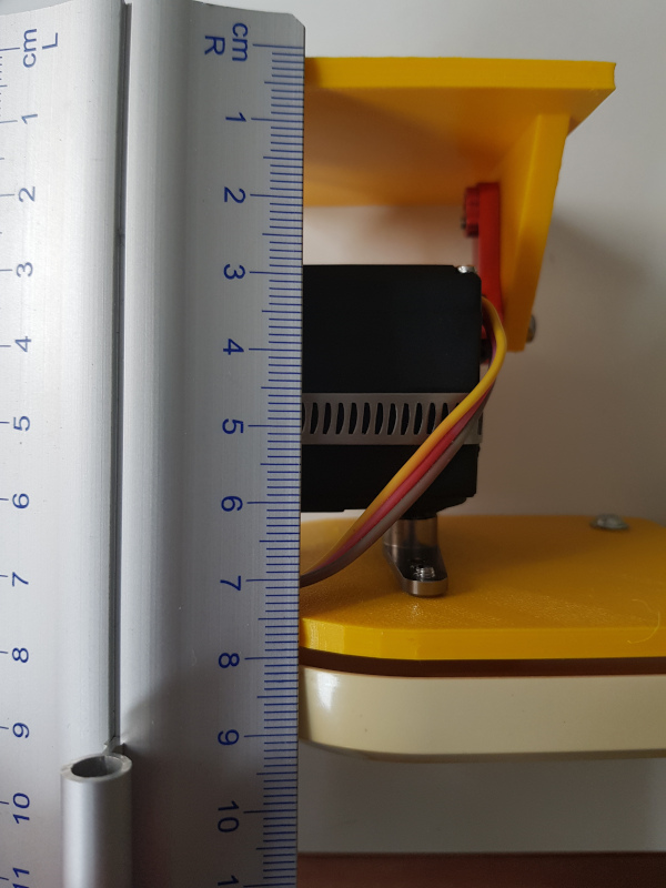
One trick was to hide the hugging servo within the body as good as possible. A next iteration could also hide the lifting servo a bit in the upper arm. For the current version, I chose to add it on a newly designed base plate that is at least slimmer than the inner should cover (compare it to the underarm):
Close up of the 3d printed 2 DoF shoulder joint on the Omnibot 5402
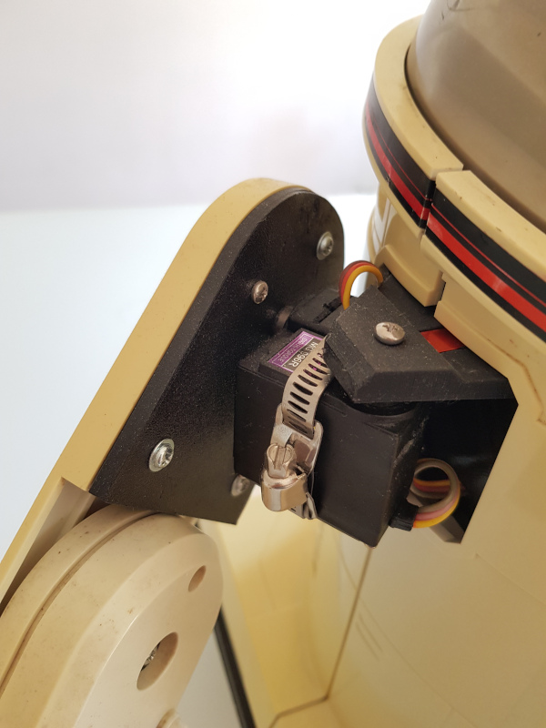
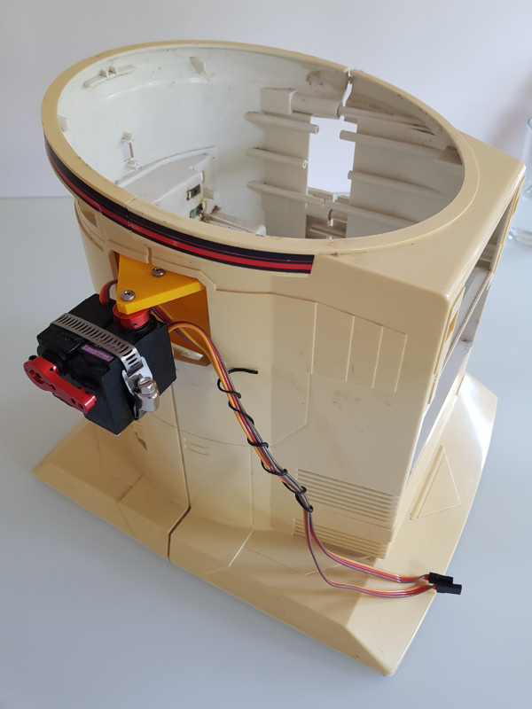
Here’s an earler version of the design, before I moved the should into the corpus:
Trashbot’s shoulders re-used in the Omnibot 5402
Software wise, I had to slow down the servo speed as otherwise Omnibot would move like this:
Single arm of the Omnibot 5402 moved by two servos without speed control
The final result are the two arms, each controlled by a thumbstick of the Bluetooth game controller. I added the Adafruit servo HAT to the stack that was using the motor stack before:
Omnibot 5402 moving two arms on two different axes using a bluetooth gaming controller
One of the things that are not making me happy is that Omnibot’s belly is to bold that it can’t close the arms and the arms are so short that they can’t lift anything that is in front of it. Fixing these two “bugs” would mean a complete redesign of the arms, I fear.
I admit: I love how home computers from the 80ies were booting up in no time. I’ve been trying to optimise the boot up time for Raspberry Pis for some time but I don’t get very far. I’m also fascinated by baremetal implementations where hardware is used for a single purpose and also works on an instant. Micropython is a nice idea inbetween as it is a “high level language” and still runs without too much overhead on very small resources.
Another thing that I’m dreaming of is to be able to write software on the go using a minimal dedicated device. My prrevious attempts comprise:
The StickPi (super small Pi Zero with an epaper display and no keyboard for ssh access from a notebook, no battery)
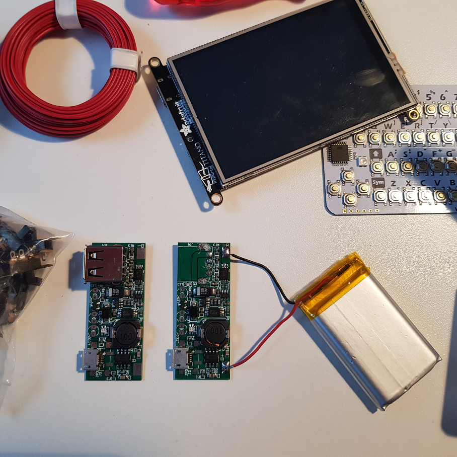
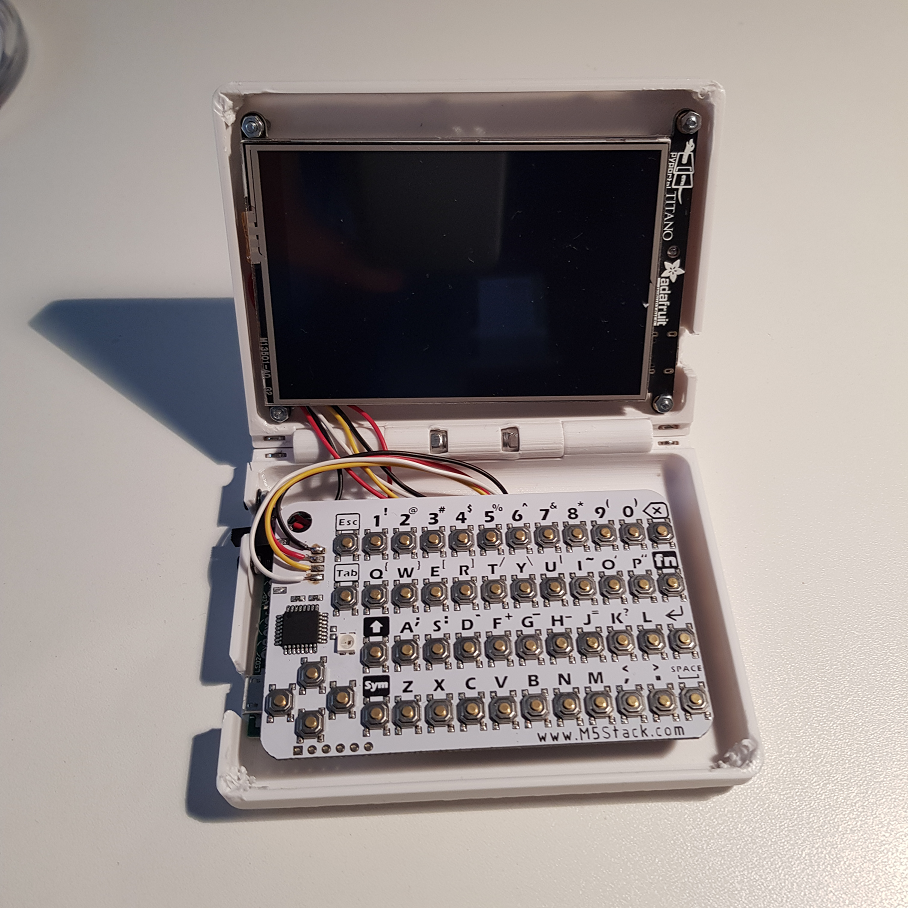
All these are Raspberry Pis in different formfactors. When the Adafruit PyPortal Titano was released, I was immediately in love as it comprises a lot of nice hardware and a 3.5in 320×480 screen that I also had evaluated for the PocketPi.
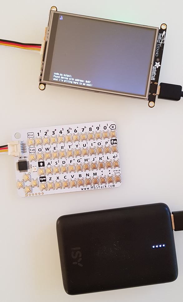
I also recently came across the hardware line of the M5Stack and their super-small and cheap I2C QWERTY keyboard caught my eye. The keyboard itself is also using an Arduino to read the key-matrix and translate the key presses to externally digestable code. So, this is my third Arduino-controlled keyboard (the recent mechanical keyboard and last week’s PsionPi). The PyPortal also has I2C connections, so let’s try it out:
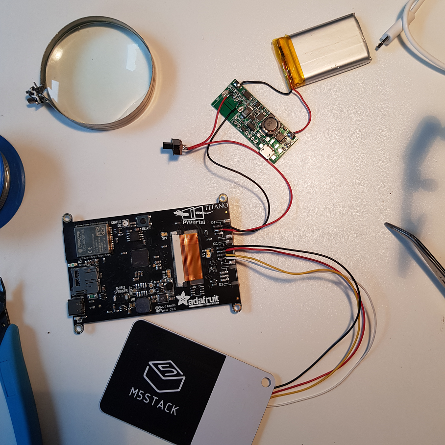
So the first thing wanted to try out is to connect the two and see if I would get use the keyboard to enter text without a host computer or a USB keyboard. The keyboard is available at 0x5f and you just need to translate the keycodes to letters, certainly you need to translate delete, backspace and return keys to the right “actions” on screen, which kind of results in a minimalistic text editor:
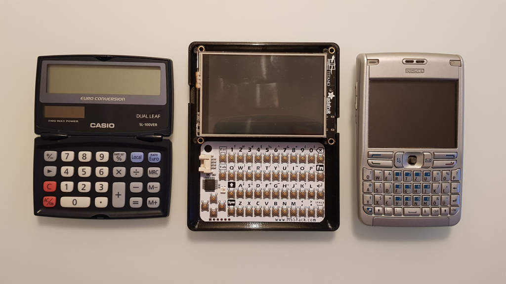
Next thing was to design a case. I never ventured into hinge design, so I wanted to keep it as simple as possible just to get started and to see whether writing code is fun or not. So I started with a slate design:
Actually, the Casio pocket calculator is a clamshell design already, but my beloved Nokia E61 is a good sparring partner in terms of design. So the black base plate is a 125x100mm design which is kind of nice, it wouldn’t get much smaller than this. I got bored with the slate immediately when it finished printing…
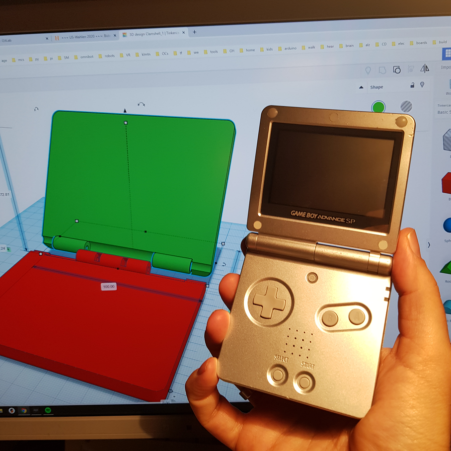
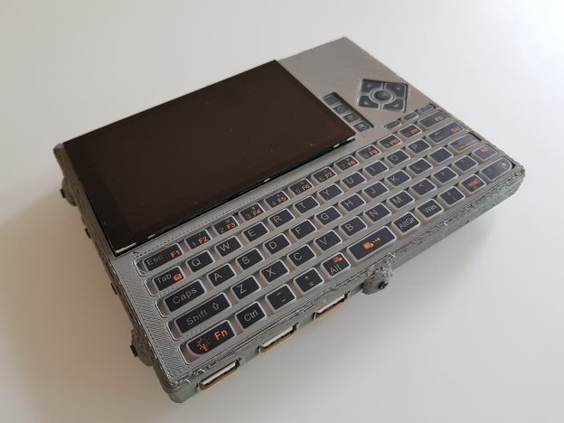
On the other hand, what was really a logical next step in terms of form factor was the clam shell design and when I had an old Gameboy Advance SP in my hand, I felt that I need this nice sound when closing and I wanted to have a computer like this. Back to Tinkercad:
Now the baseplate has 100x80mm and the hinge is working really well. I also added magnets on all corners to keep the states stable but they are not strong enough and take up valuable space.
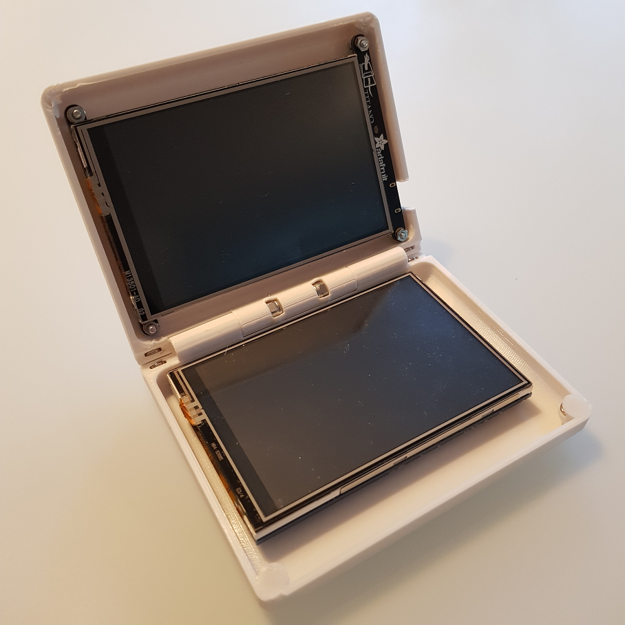
Just for fun, I pulled out my old screen from the earlier PocketPi iterations:
To make this usable, you’d need to add the Pi Zero underneath and power both with a battery plus connect them somehow (not via Wifi 😀 ).
Next it was time to design the power source. This time I didn’t stick with the Adafruit powerboost, I think it is too expensive and it gets fairly hot. I had a couple of cheaper but larger charger boards in a drawer, so I decided to give them a go. To save height and space, I removed the USB plug:
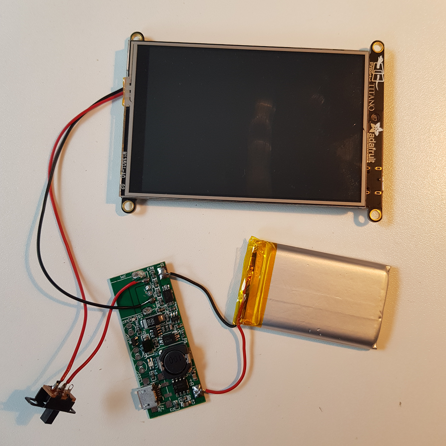
To save height, I also removes the plugs from the pyportal and wired the power cable directly, following the wiring scheme from Adafruit:
Finally, I also removed the plug from the M5Stack keyboard and soldered the cable directly:
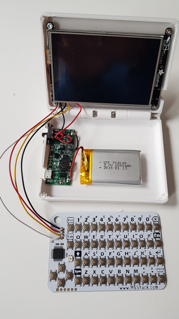
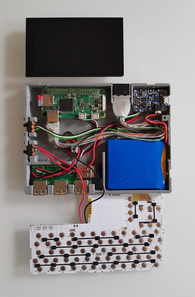
I had to modify a couple of places of the original case design and cut out the plugs for USB-C / pyportal, the power switch and the micro-USB charging port, then it was time to fit the power circuit:
Finally, the keyboard is added using a double-sided tape:
And now the little darling in action:
I wrote a little file lister in python as well as a minimalistic python editor. The problem at the moment is that you can’t write to the on-board flash when hooked up to a host using USB-C. Need to check out now whether it works when the device is battery powered. Stay tuned!
UPDATE: I just polished the case design to actually close properly and removed the magnet holders to give the innards enough space. Files are published on Thingiverse now.
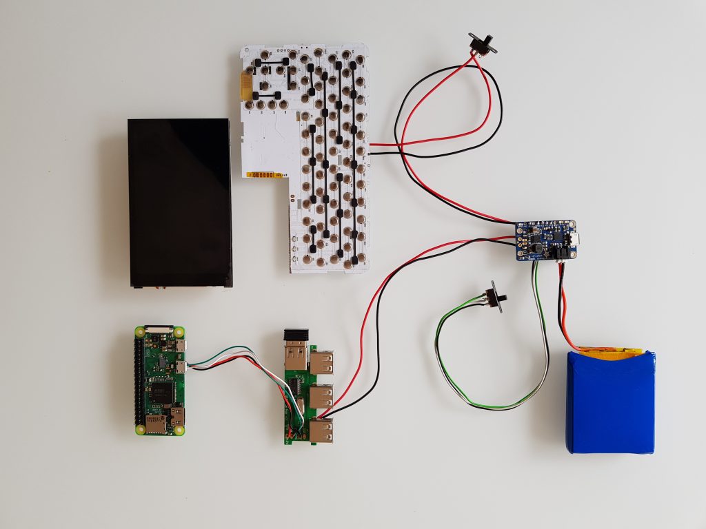
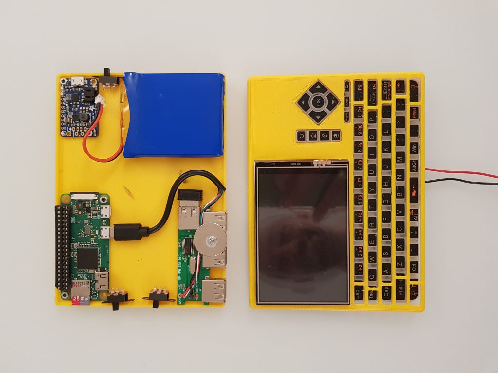
TL;DR: 14x11cm portable Raspberry Pi Zero W with 3000mAh Adafruit powerboost 1000, Hyperpixel 4inch display, a keyboard and a4 port USB hub. Scroll down for videos, STL files, shopping list.
I always want to be able to carry a little computer around that reduces the outside distractions, like no email, ideally no browser, no messaging, etc. Actually, I enjoy the “silence” that I have with the Raspberry Pis. They allow me to focus on writing software for robots and the like.
Sometimes, you want to code on the go. My second shot in that direction is the StickPi, a little computer without battery but with an e-paper display and a couple of buttons. I actually keep using it, it’s my most used self designed computer.
My first shot hasn’t been published yet: the SlatePi. It is a 5inch computer with a small keyboard and a 4000mA battery, but it seems to be to large for every day use.
So I did another computer: today’s PocketPi. It is the symbiosis of the first two: portable but still a full keybard and a battery included.
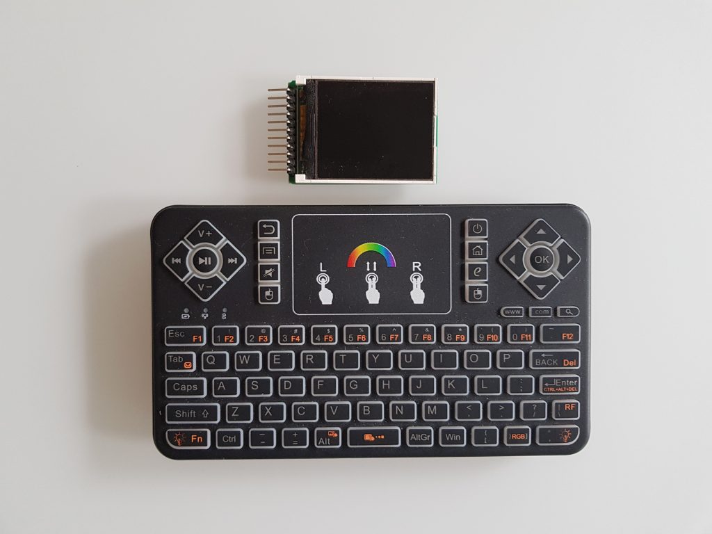
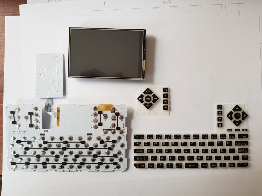
It all started with the idea to build a Pi Zero and a display into my favorite mobile keyboard:
I wanted to replace the mousepad with that display.
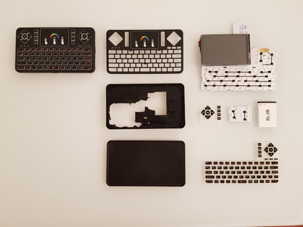
So at some time, I started to decompose that keyboard to understand how much space is there to actually fit in a Pi Zero W, battery and the display.
the decomposed keyboard and already cut off left part of the PCB and softkeys.
I quickly learned that a) the inclusion of the driver for a ST7735 1.8inch display is cumbersome and the resolution might actually not be nice for really working with it (128×160), it may be better suited for a retroPi machine.
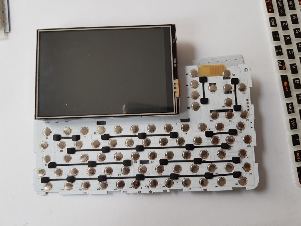
So I decided to use another display that I had at home already which is a 3.5inch display for the Pi (without HDMI) and some more decent 480×320 resolution.
[I also removed the original battery plug and the keyboard’s switch to reduce height.]
However, I didn’t want to increase the size of the device by the height of the diplay and thus decided that I don’t need the left (media-related) buttons of the keyboard:
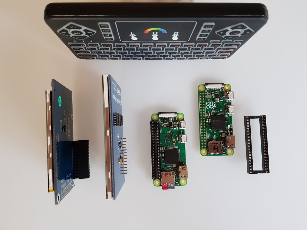
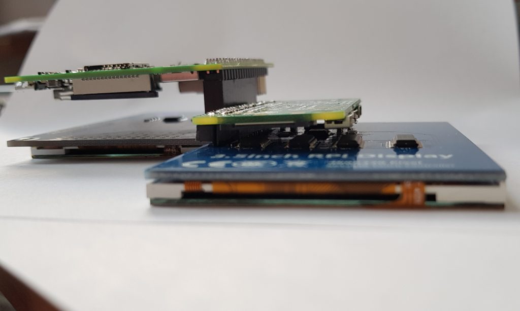
Another thing was to ideally keep the height of the original keyboard which is about 12mm, but looking at the standard plugs of GPIO displays, it became clear that I need to apply some tricks:
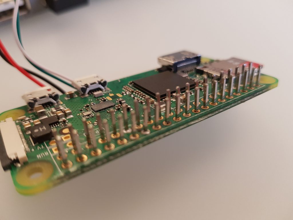
plug deprived display, pi with a plug
I soldered the rails of a DIP plug to the pi, took away the whole plug from the display cutting off the pins to a bare minimum.
great height reduction.
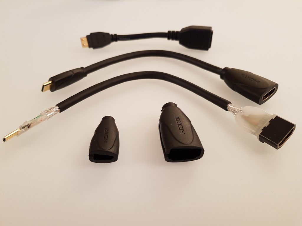
I also decided that I wanted to have a full size HDMI out so I bought shorter and more flexible cables than I had at home and dismantled them:
decomposing an HDMI cable reduces weight and increases flexibility.
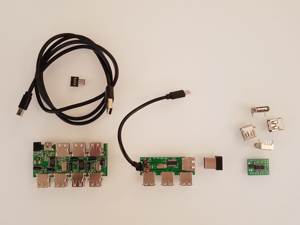
Finally, i also wanted to add a decent non-OTG USB to the machine as OTG adaptors simply SUCK.
Different USB hubs to select from.
I actually went with a little board that included the OTG “logic” already and had one USB on the side to actually keep the keyboard receiver and stay within the devices case.
before dcomposing the USB 4 port hub.
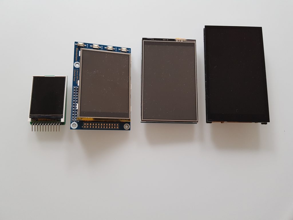
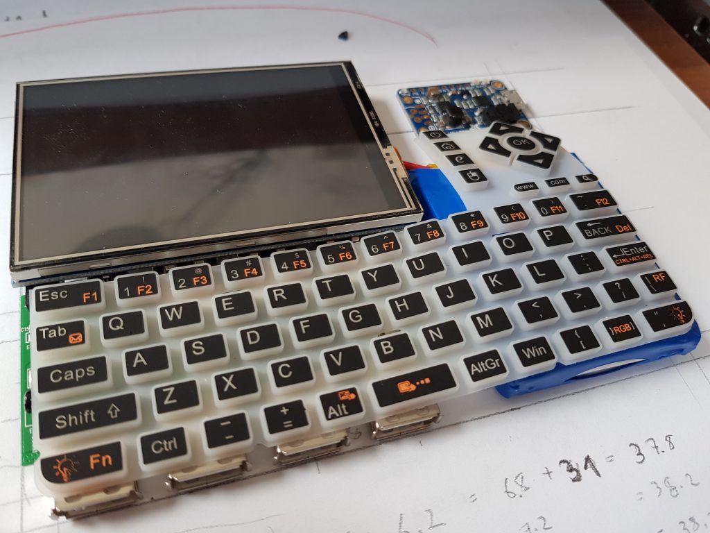
During the journey, I decided to upgrade to the final Hyperpixel 4 inch display, with a decent 800×480 resolution. The advantage is the little increased size (4mm) compared to my 3.5inch before plus it can be switched off via GPIO. So this is the evolution of the displays over the project:
1.8 inch, 2.8 inch, 3.5 inch, 4.0 inch
I also added the Adafruit Powerboost 1000 and a rather flat 3000mAh LiPo to the mix. The Adafruit is rather expensive (20-30€) and only supports 1A charging current, I’d love to have a cheaper charger board with 2A at some point in time.
With the power source in place, it was time to wire it all up. Note that I added another switch to the keyboard so that I could switch off the keyboard but let the Pi run for background computations.
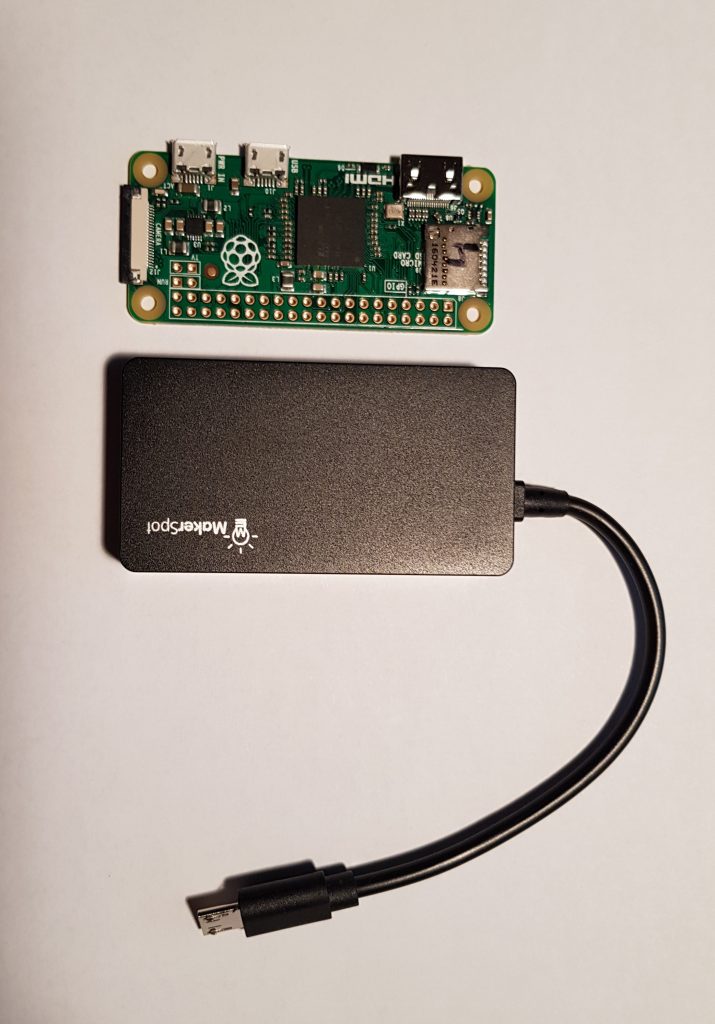
As you can see, I wired the USB hub directly to the Pi to save some more weight and space:
Wiring the OTG USB hub directly to the Pi.
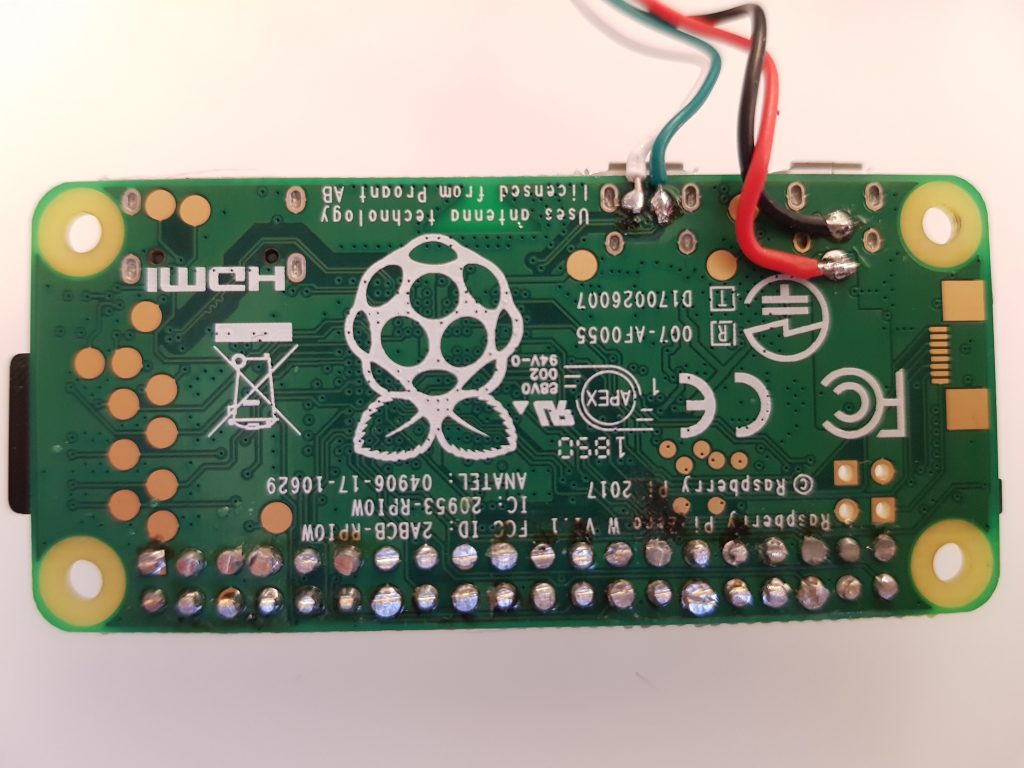
Another trick to save height with also the new Hyperpixel display (the plug of the screen is okay, so I needed a new Pi Zero without the DIPs and just short pins), is to solder the pins with the plastic spacer from behind and then remove it plus the excess pin lengths on the back:
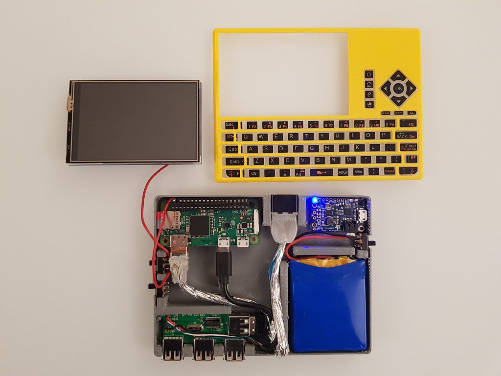
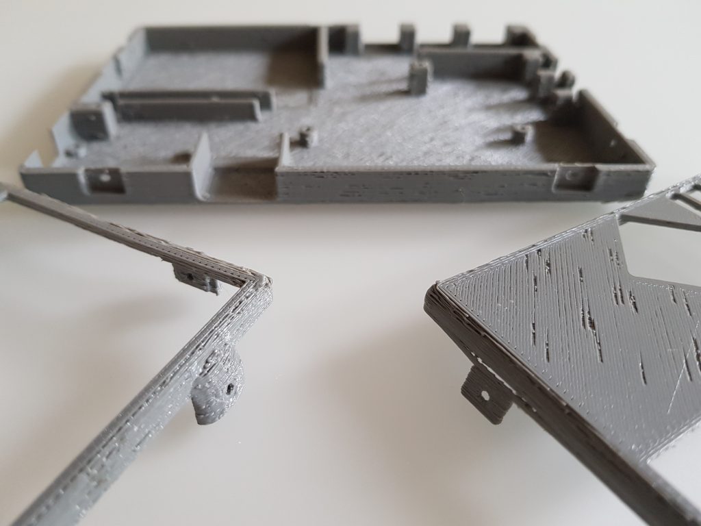
After the system was established, it was time to design the case and get a feeling for the locations of everything:
[earlier version with the 7 port USB hub and 3.5inch screen.][earlier version with the 3.5 inch screen and first attempt to make the display switchable.]
A later version then had spacing elements between the components to hold them in place. Also the HDMI output cable was added then:
As mentioned before, the screen switch for the 3.5 inch didn’t work as you could switch it off (cutting off 5V with the physical switch) but not on again since the OS wouldn’t re-recognise the screen then.
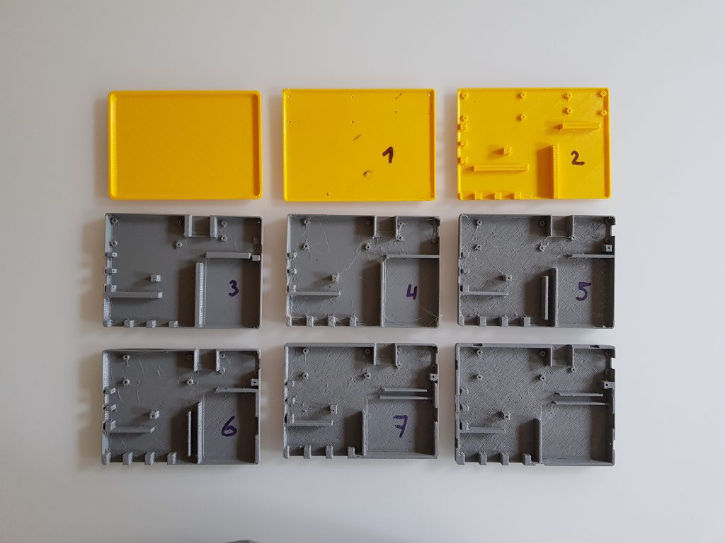
So the whole case design (TinkerCad) underwent a couple iterations:
As you can see in iterations 7 & 8, the battery was rotated 90° to landscape and the HDMI cable is going between battery and battery charger.
During these iterations the device grew a bit in dimensions to a final 11x14cm. That’s 3cm more than the original keyboard’s case at 8x14cm. But anyway that’s the price for a 4inch screen with a 800×480 resolution…
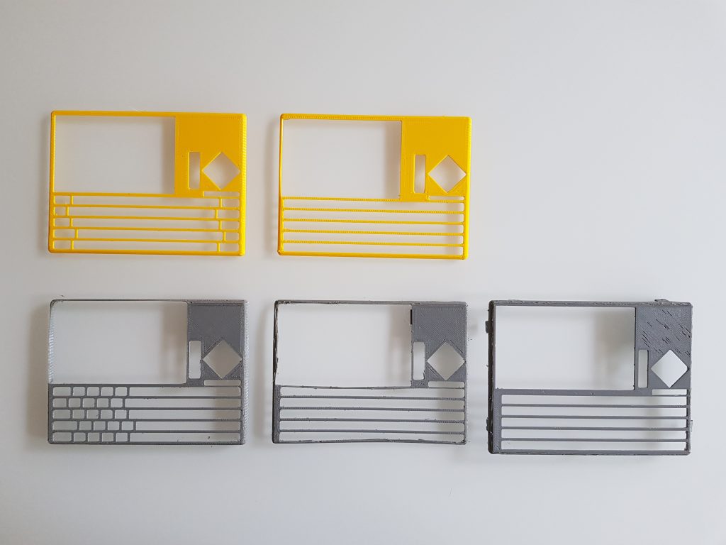
designing the holes for the keys is a pain in the butt…
So that’s the currently final layout:
Time to look at the functionality in a video:
FIRST BOOT UP!
As I wanted to take the PocketPi to my easter holidays, I needed trade the flat screw “lips” to be bold and rounded to give the hole thing more stability:
bold screw holders, not nice, but survived the holidays / travel.
I installed Raspbian Stretch lite and added the Pixel desktop plus Geany as python IDE. I also configured two of the buttons to zoom the text in Geany, the right mouse key on the keyboard is really handy, the touch screen works as left mouse button and I added multiple desktops to easily switch between apps. Here’s a video of the currently final device in operation:
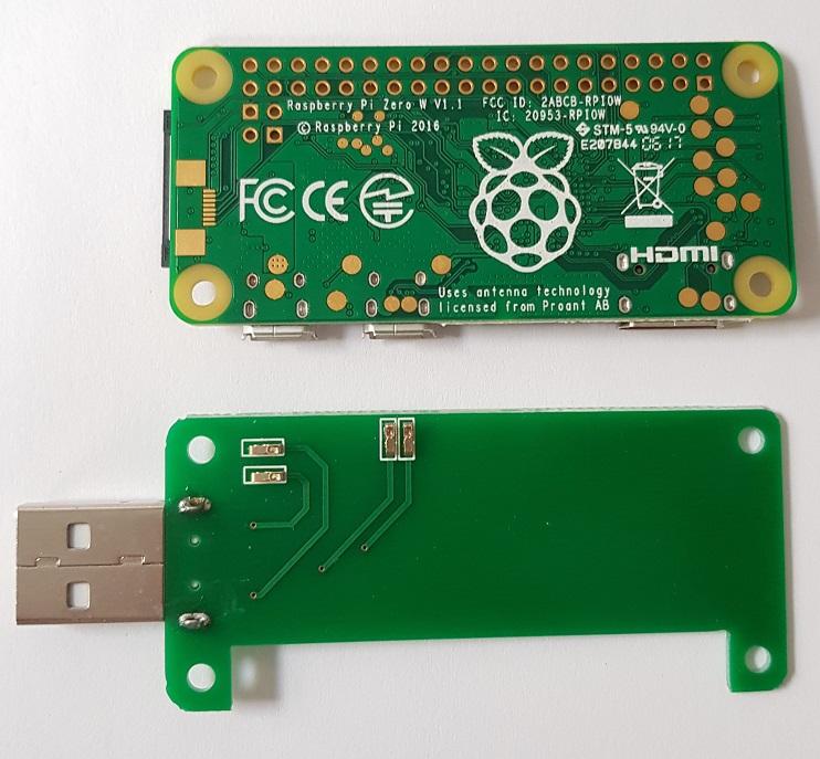
Then I came along these USB boards that you can pogo-pin to your Pi Zero which is similar in design to what the guy at NODE did.
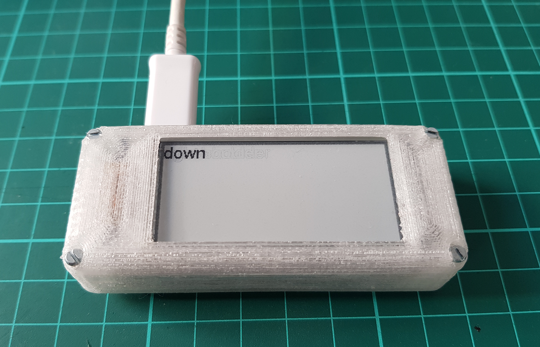
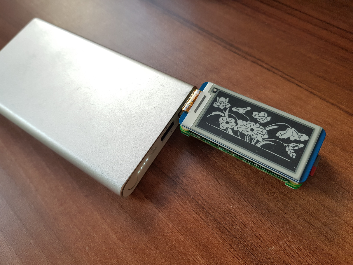
When working with a Pi Zero, I wanted to connect via VNC so I can run Pixel desktop and Geany on the Pi to develop and run software. When doing so, you quickly want the Pi to display the Wifi and IP address it’s connected to. I chose an e-paper display from Waveshare (do yourself a favor an buy the balck/white display only, not the one with three colors as they don’t support partial update, i.e. they refresh very slowly!) and bought such a USB power board and attached the Zero to a battery:
Once you have this kind of display, you learn that the physical interaction with the machine is one way: consumption. And immediately, you think that it would be nice to have interaction methods to select a WIFI or shut down the machine or select operation modes, etc.
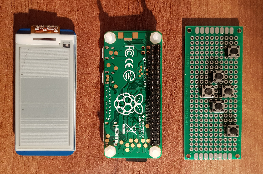
So I sat down and designed a PCB (not printed but wires on a protoboard with a pretty ideal size), to add some buttons for directions as well as two “shoulder buttons”:
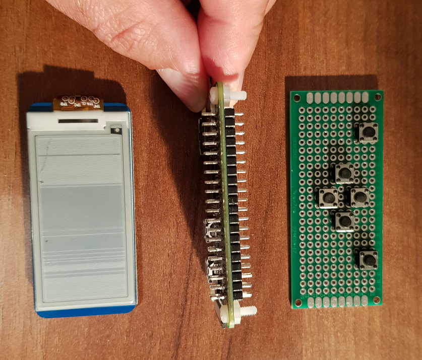
To keep the design compact and as the e-paper display would consume the full GPIO, I soldered the pins on the Pi to go through the PCB:
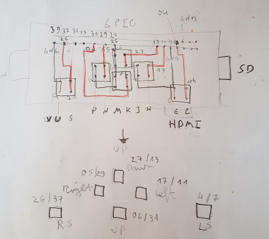
I chose a wiring that can actually use buttons without additional resistors and so the whole system works with only input ports as well as GND:
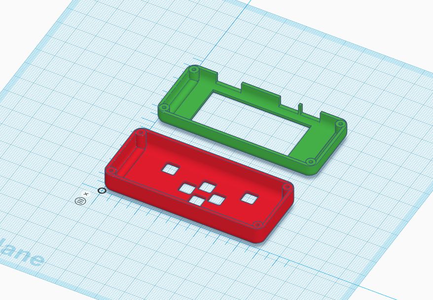
This led to a compact design alltogether, see also the first version of a PETG designed case:
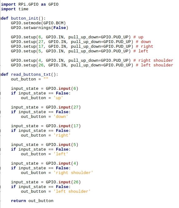
There is still room for improvement for the case but right now I’m happy enough with it to actually keep it and write software. Querying the keys is really easy:
Finally see a little interaction of the buttons and the screen here, the software is really simple to query the buttons continually and display values on the e-paper:
(On the top left, you see the Raspberry Pi 3 case with the keyboard integrated, still not happy with that design, that’s why I haven’t published it yet.)
I may venture into actually designing (EAGLE files) and ordering PCBs for the button to make the whole thing more “defined” and better fitting the case.
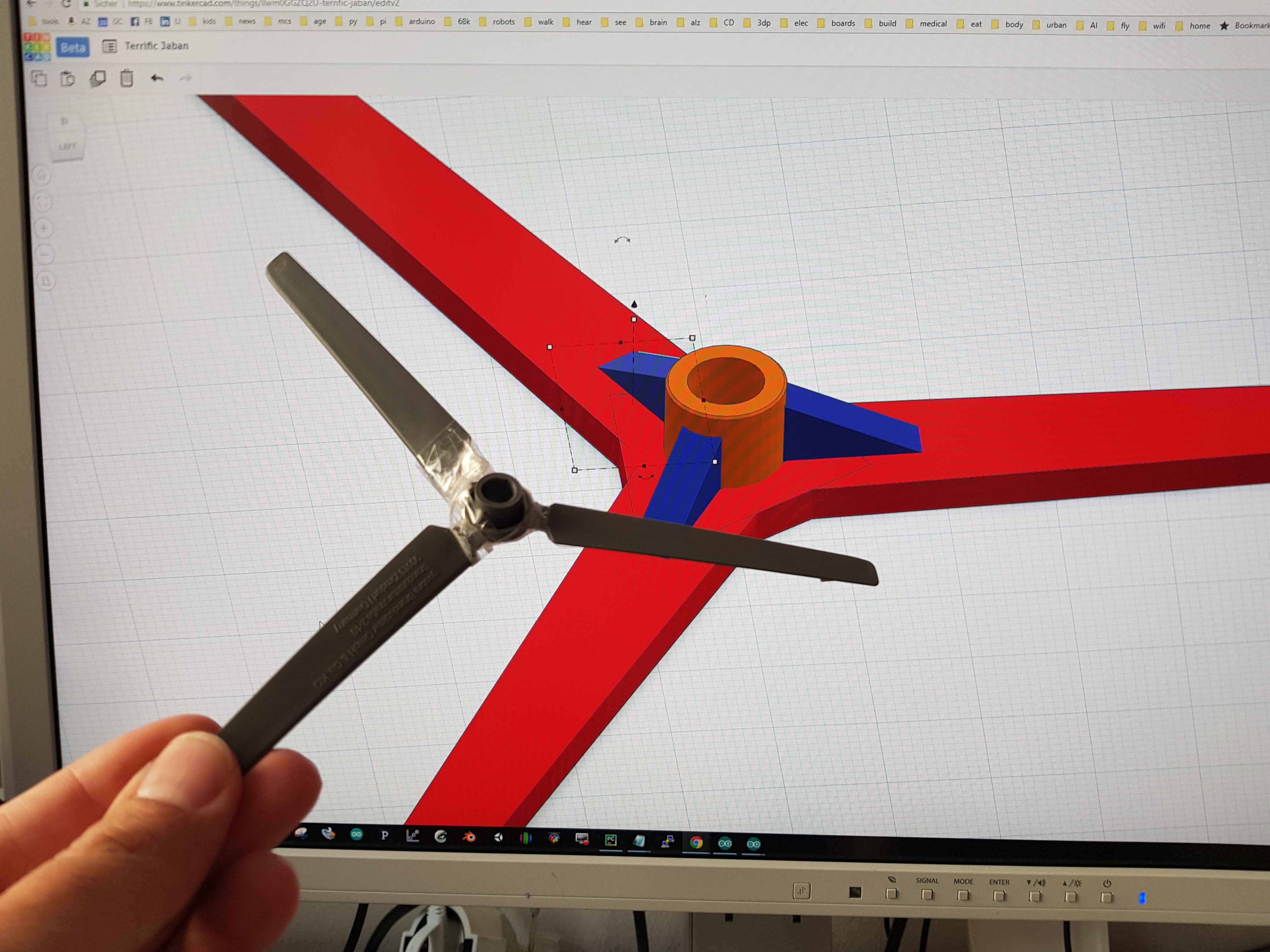
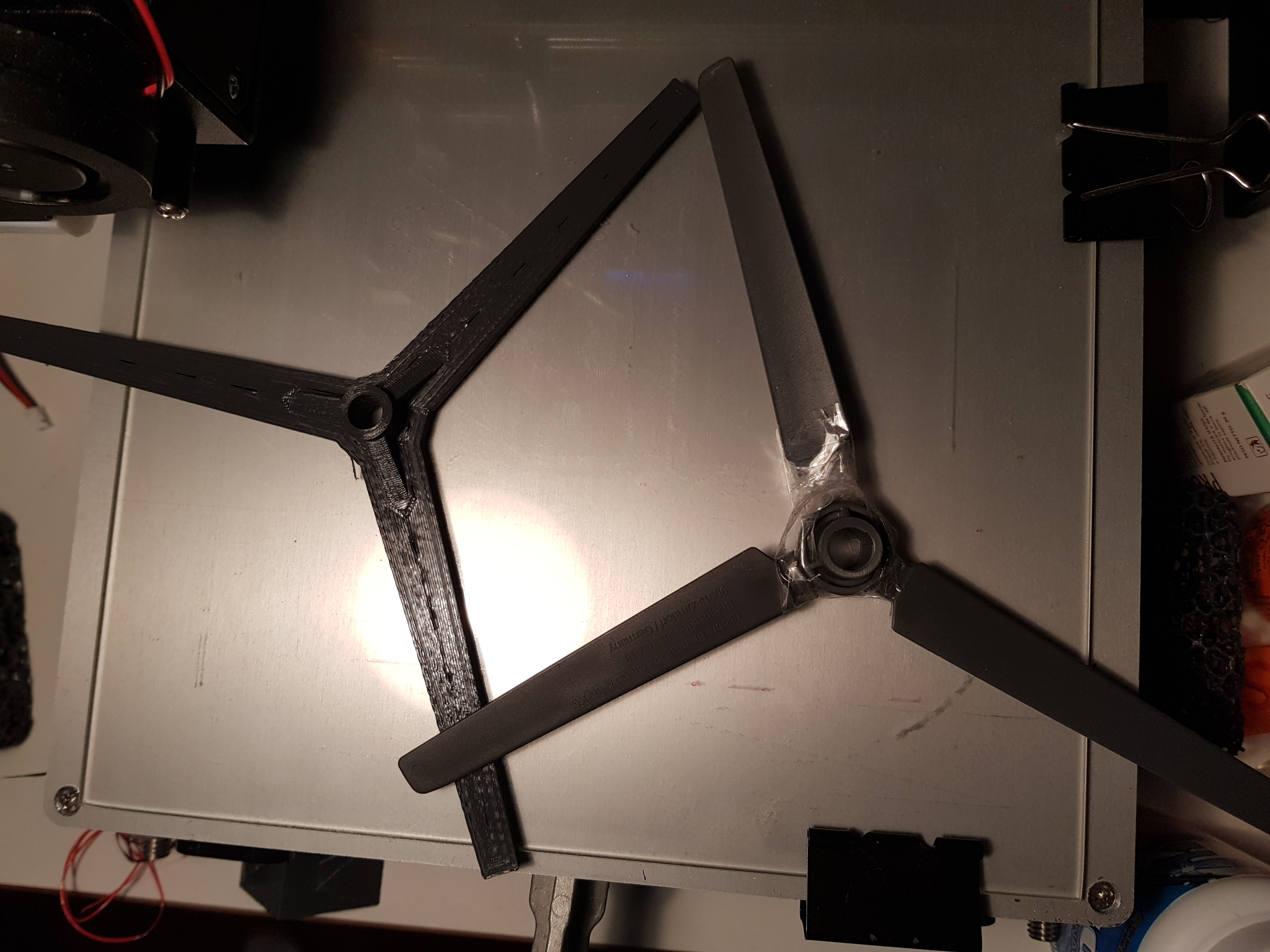
The rotorblades couldn’t resist my kids, so there was the job to 3d print them. I did this in 40min in Tinkercad, I certainly did the connection of the blades in a different manner than the original, you see that the blades are connected even around the shaft. I also added those blue supports that should give additional strength.
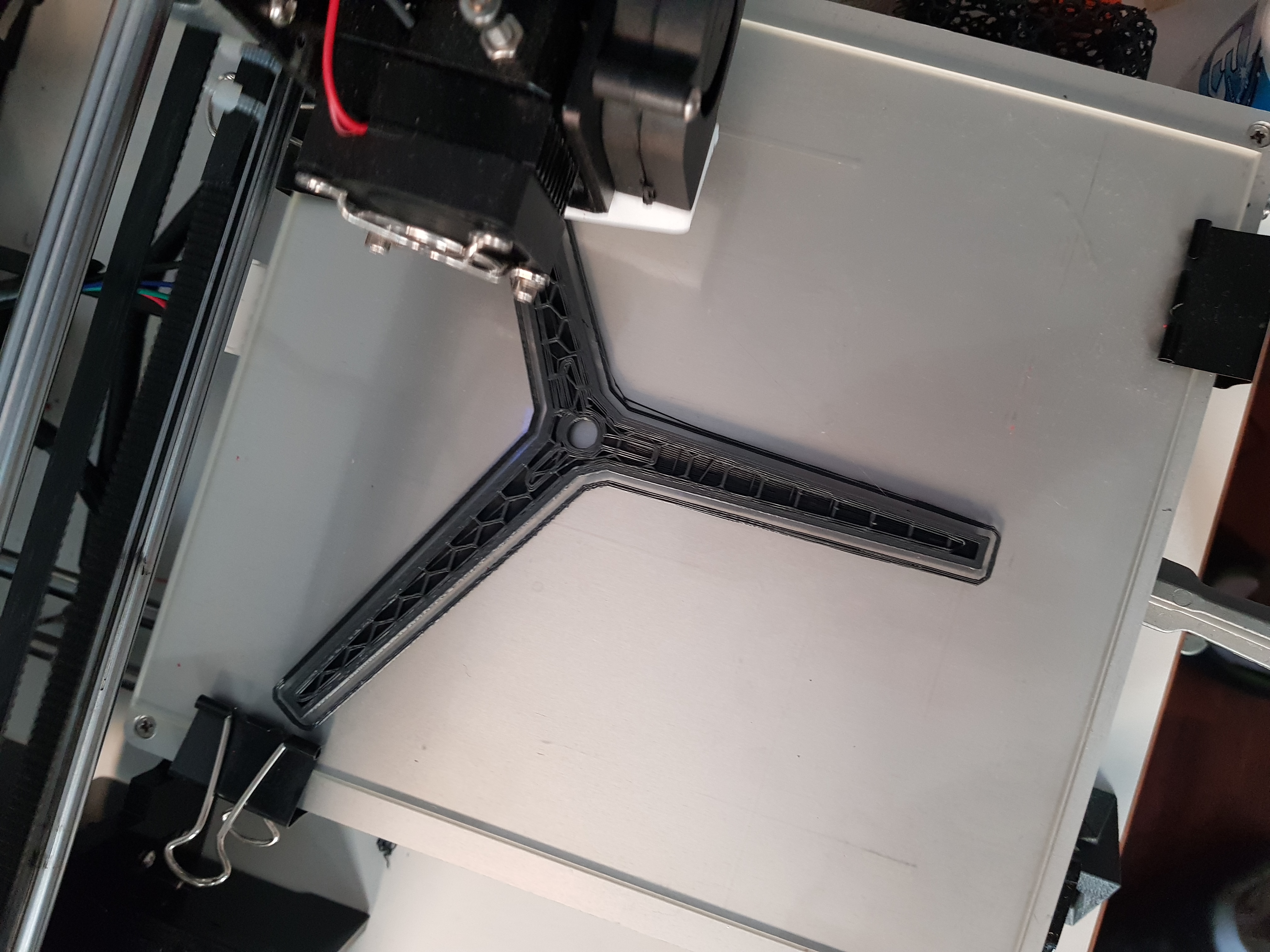
Anet A8 printing the bad boy in grey, similar to the orginal:
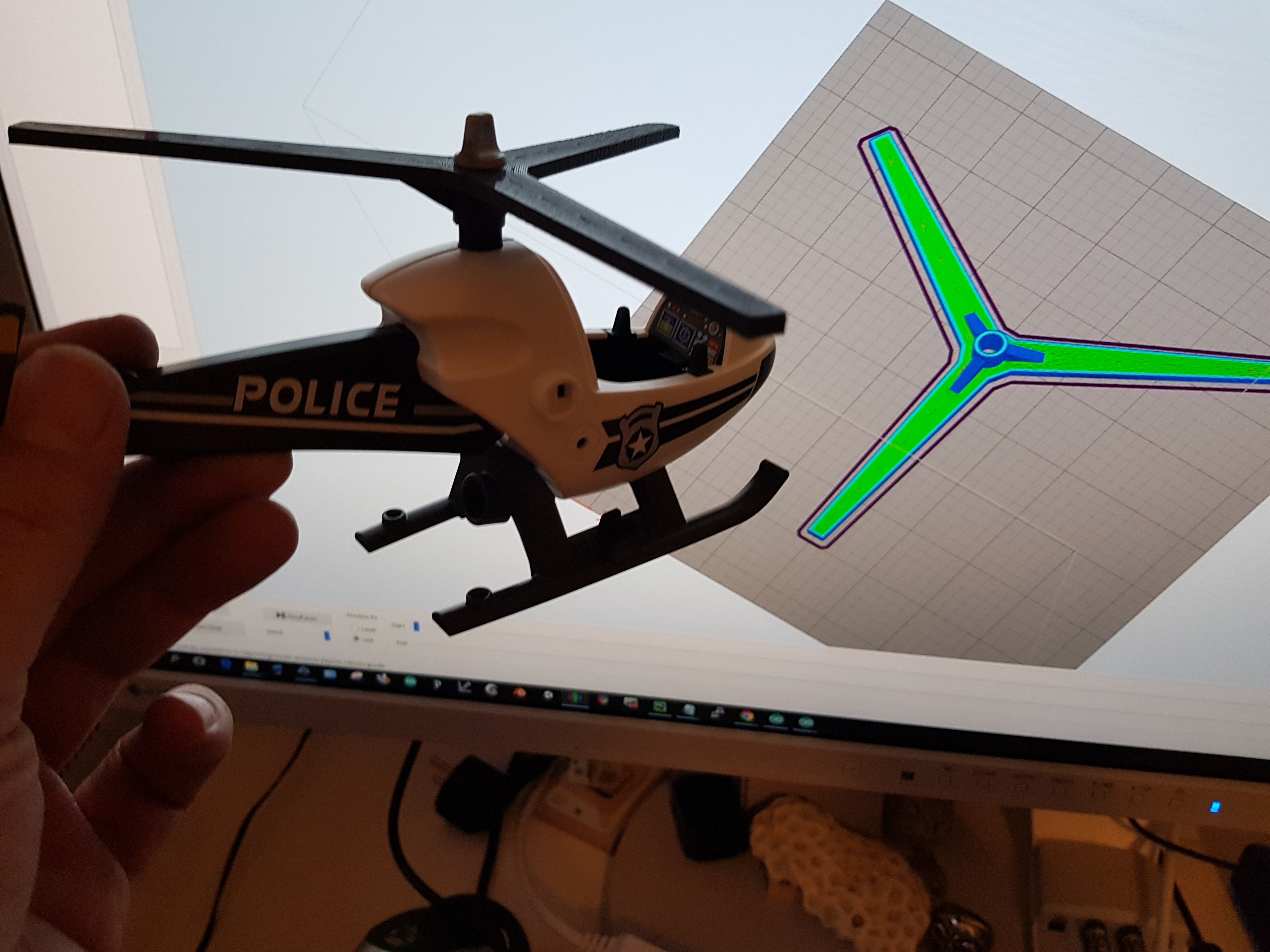
You see there is some infill structure, I hope the rotors will last better than the orgininals, I also made them 3mm thick which is about double the original. But PLA is also a bit crisper. The two together:
And the new blades on the helicopter (about 40min print, via Octoprint):
In the back you see the rendered gcode file in Simplify3d. Nice One and a half hour repair!
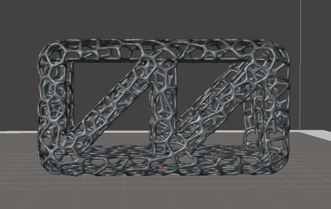
In this post I compare all three versions of my light weight structure experiments, with a couple of pictures an descriptions that were not given in the video below:
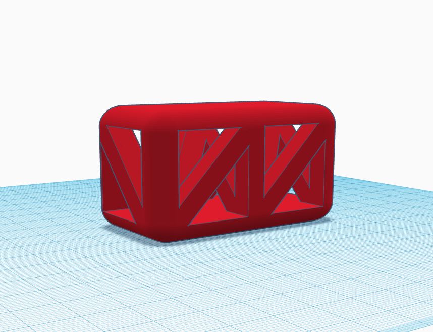
Version 1 had no roof and floor holes and that created the problem for the printer, also, I was printing the PLA at 200 degrees. I learned that lower temperatures are better for bridge structures. Download both files on Thingiverse.
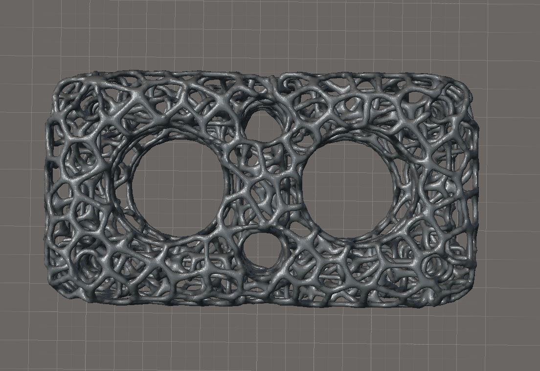
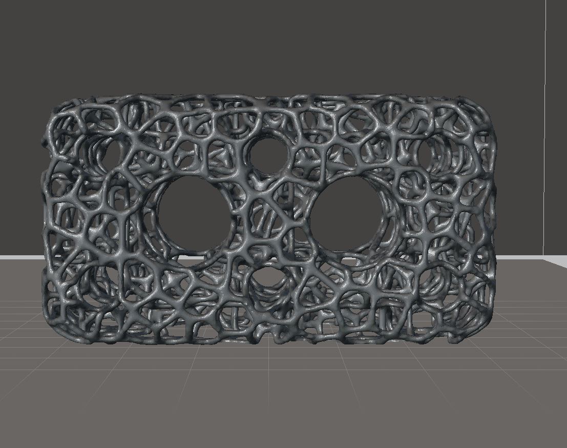
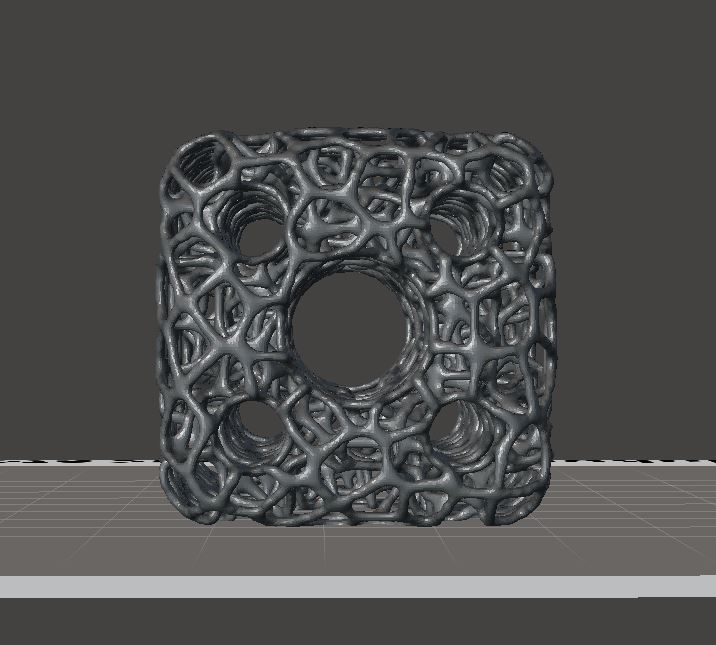
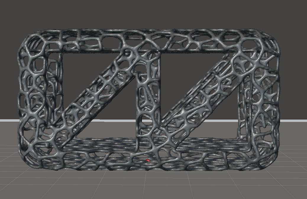
So, for version 2 I decided to work with round holes in all three planes, cylindric holes always yield a more organic appearance compared to triangles / prisms and I want to get more organic looking structures. Download version 2, solid and vorony version on Thingiverse.
Version 3 is a refinement of version 2 in that the smaller holes are bigger in diameter to better distinguish them better from the Vornoy holes generated automatically. Also, a greater diameter yields more surface to add the organic structure. Finally, I reduced the center holes to get a better average “wall” thickness, i.e. the distance between a hole and another hole or the sides from the box. In this way, the printer had a better chance to actually realise the Voronoy holes between the cyclinders.
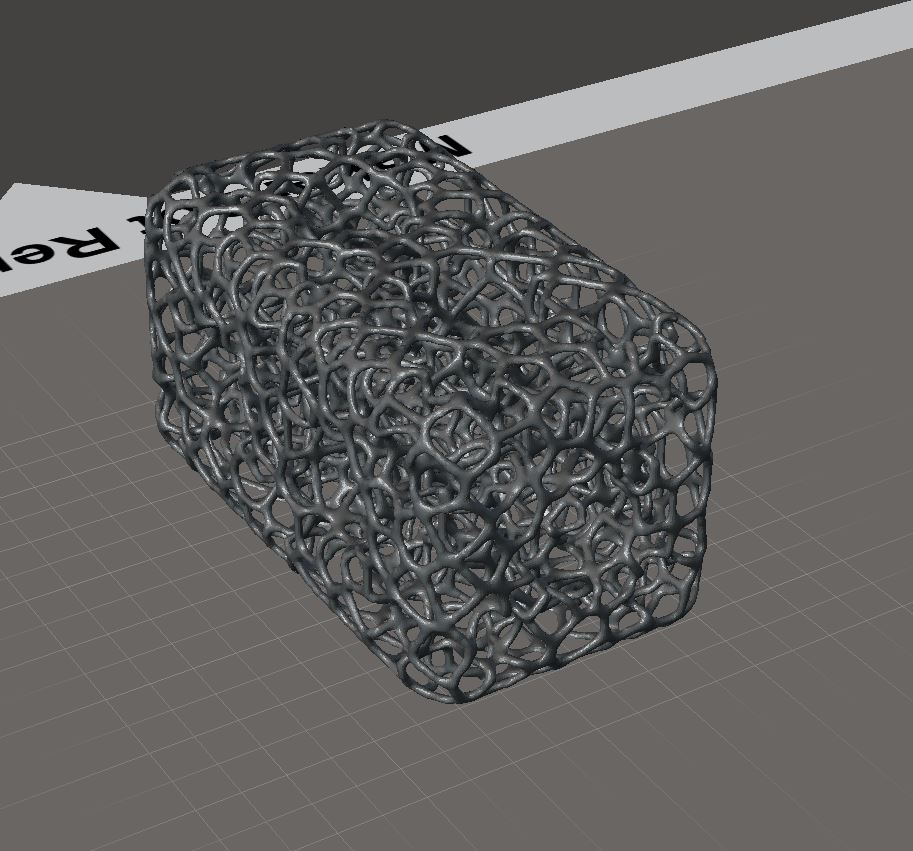
Finally, I produced the Voronoy version with a thicker structure, meaning that the lines were thicker and ideally the printer has a better chance to “find” them again in the next layer:
I also reduced the printing temperature to 190 degrees from layer 3 on. The first layers I printed with 200 degrees to allow for a better sticking to the heat bed. I changed the bed to glass and used glue stick. These delicate structures have only a couple of touch points with the headbed so it is of outmost importance to have them sticking well. The servo housing shown in the end of the video was printed on pure glass without glue or spray, but the organic structures need more attention…
I recently bought the cheapest a Prusa i3 clone on the planet, an Anet A8 at gearbest. Lovely to build and certainly great for an electronics hobbyist / maker. I never would buy a 600 or even 2000€ printer today, since I don’t think to have many usage scenarios.
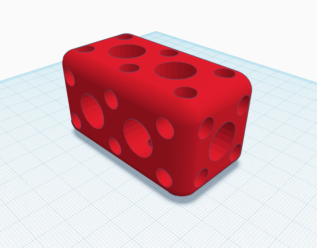
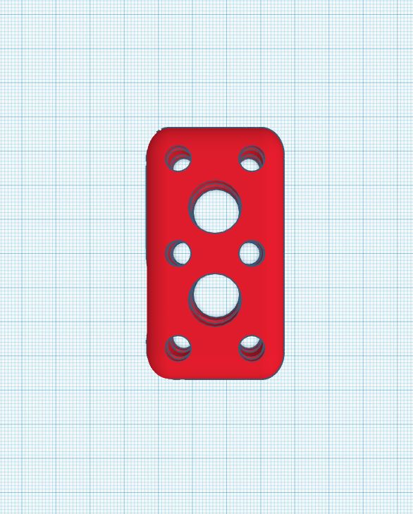
But there was always one dream: to print “bones” for my walking robots to make them lighter and more “bionic”. So one of the first things I designed on Tinkercad was this structure:
I’ve been searching for a while to make structures more “bone”-like, i.e. some kind of organic or cell-like holes into them. That’s not too easy.
One tutorial I found is working with Autodesk Meshmixer. a software that is really nice to work with 3d models and view them. The tutorial leads to such structures:
The problem is that this depends on the amount of points given in the 3d model itself and tessalating them is cumbersome imho.
Another software I found is the Voronoization Online service which is EXACTLY what I want (upload STL, set parameters, download STL, bang!). The point is that you don’t care about the points of which your model consists:
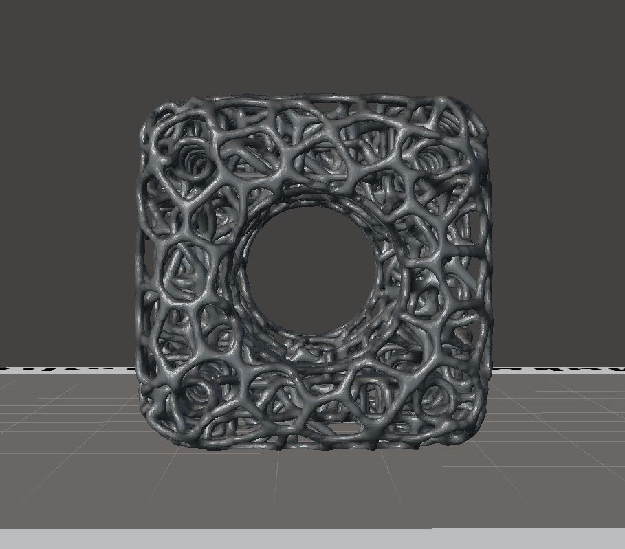
And here’s the video comparing the solid version and the Voronoy version:
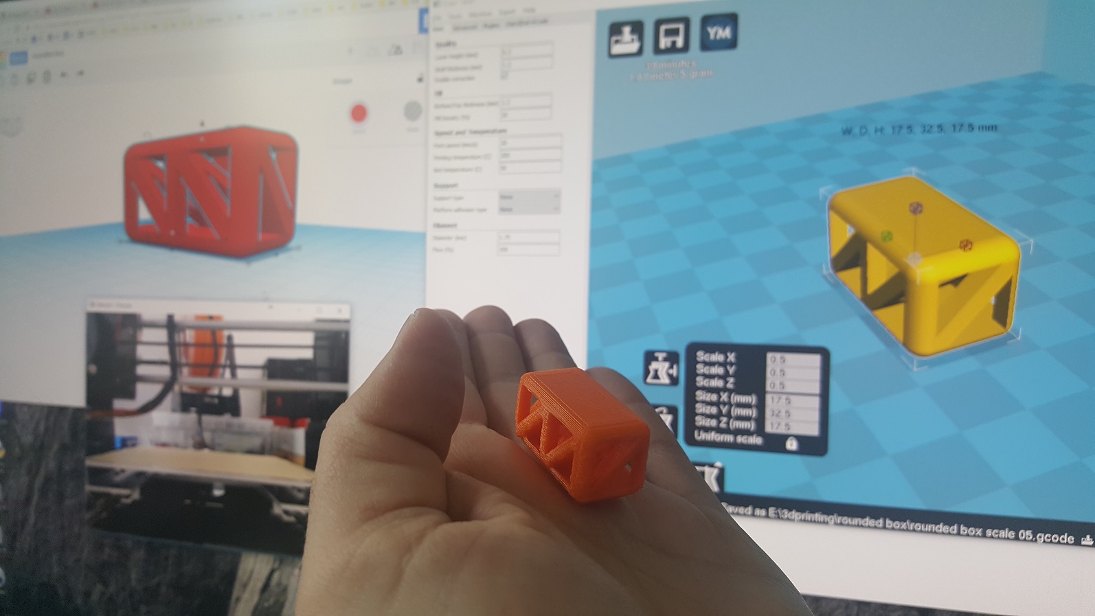
This 6x3x3cm structure has a weight of five grams, it’s 20% infill, 3×1.5×1.5 solid sibling has six grams (but of course the solid one is MUCH sturdier).
I’ll now get into testing these parameters and understanding them in the context of 3d-printability. Exciting!