Category Archives: Allgemein

Omnibot 5402: Adding LED matrix eyes and computer vision

The next important thing was to give the robot more personality and I found one or two chaps in the internet that worked on LED matrix eyes. But I also wanted to get computer vision to Omnibot so that it could see things or people and potentially speak to them, grab them or move towards them.

So let’s start with the decomposition of the original eyes which basically had a little lamp build in:

Omnibot 5402 head plate with reflectors, lamps, distortion plate and color filter

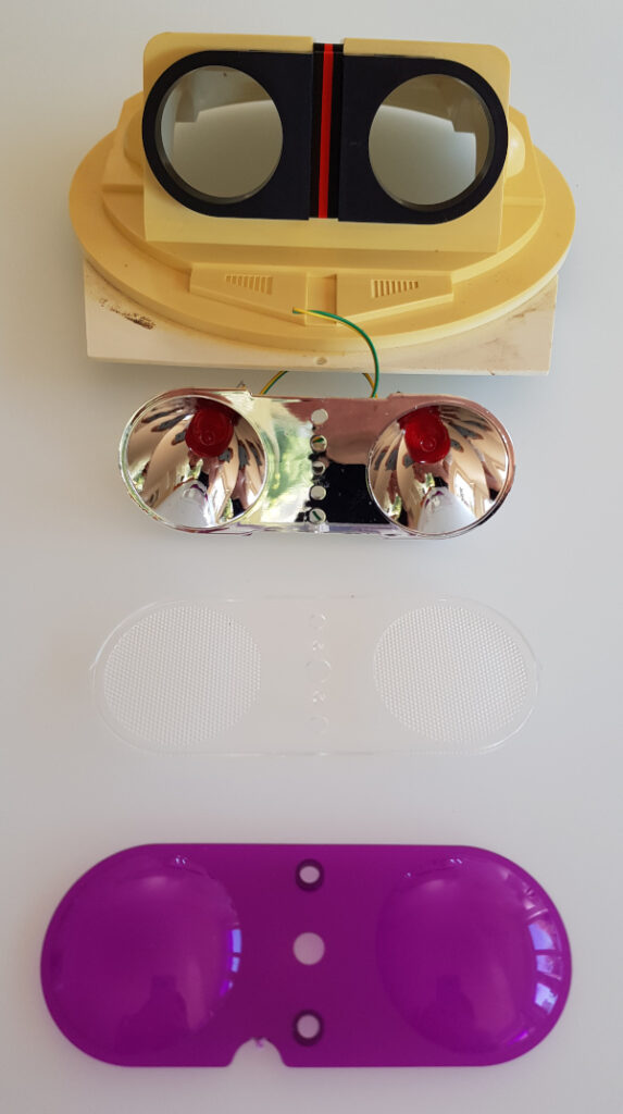
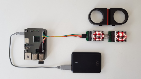
I decided to just keep the head plate and the black adapter and replace all other parts. Next I soldered the two 8×8 LED matrices, they are chainable and adapted the code from the above link.

Minimal expressive eyes (MEE) for the Omnibot 5402 powered by a Raspberry Pi 3.

This was very satisfying as there was a quick success. However, as you can see, the MAX7219 controller chip is standing out of the black adapter, making it impossible to build the eyes into the adapter. So the next iteration was to desolder them again and rotate them 90 degrees…

Rotated LED matrices and a 3d printed adapter from square to round.

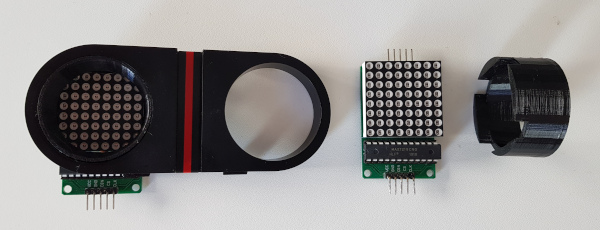
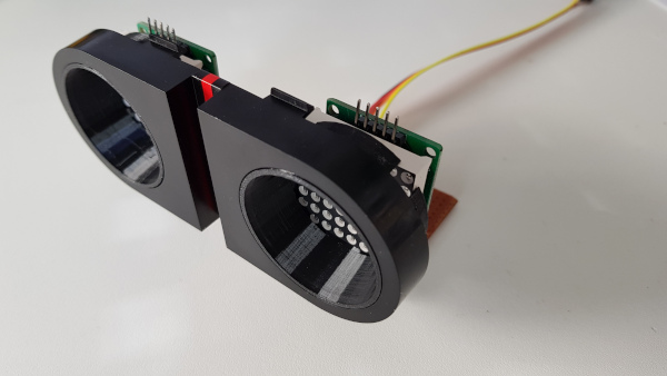
I also decided to design a 3d printed adapter to keep the squared matrix in the round hole.

Original black Omnibot 5402 eye plate with black 3d printed adapters and the 8×8 LED matrices in place.

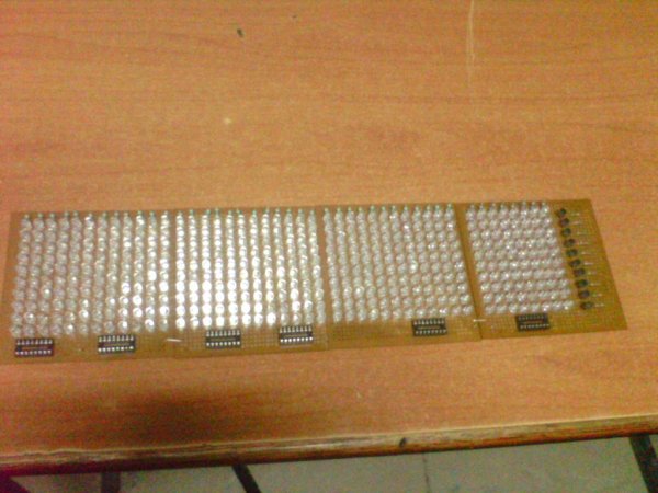
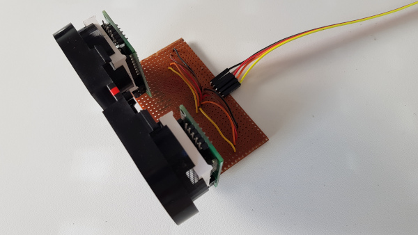
I also had to connect the two LED matrices differently as the pins would look downwards now. I decided to use a perf-board that I had in my cupboard from since my teenage years, so it would match the Omnibot in age 😀

Two LED matrices on perf-board and cable to the Raspberry Pi.

A little software experiment yielded this:

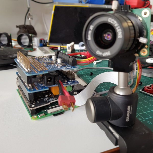
When I was working on the Omnibot’s eyes, the high resolution Raspberry Pi cameras were launched and I had to buy them immediately. I don’t really like the flimsy design on the original Pi cams.

The two objectives for the two 10 MP Raspberry Pi cams.

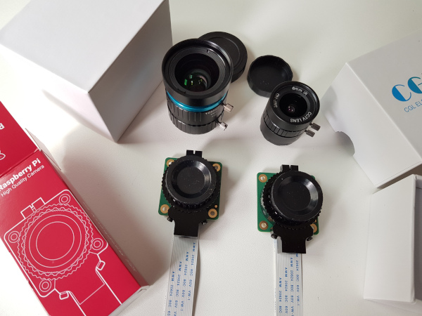
I decided to use the fish eye lens as it is small enough and would broaden the Field of View of the Omnibot.

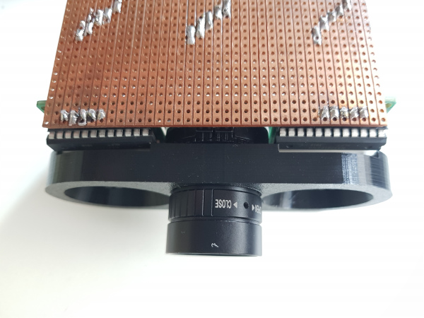
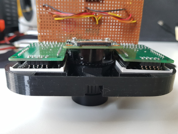
I realised that the original black Omnibot adapter certainly has no hole for the objective, but I definetly wanted to have the camera very close to the LED eyes. So I decided to do away with the adapter altogether and re-designed the whole adapter to keep the objective as well. This was not too easy as the diameter is really huge and I wanted to keep the matrices at a maximum in size.

10 MP Raspberry Pi cam with fish eye lens in the next iteration of the Omnibot 5402 adapter.

Finally, I also had to match the PCB with the matrix PCBs which also was not too easy. But luckily, it worked out:

LED matrices, fish eye lens as well as all three PCBs in the 3d designed adapter.
PCB view of the Omnibot 5402 eye adapter.
Optimisation in height vs overlap was hard work.

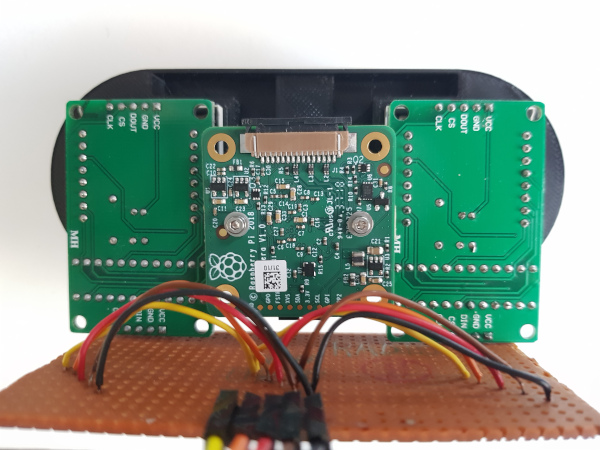
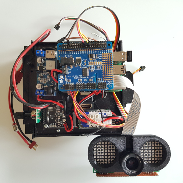
Finally, I had to buy a longer cable to connect the camera to the Raspberry Pi that was mounted on the Omnibot 5402’s tape recorder base plate in the meantime.

Hardware stack of the Omnibot 5402: Raspberry Pi 3, relais board to switch components, servo controller for the arms and motor control board for the wheels.
Eyes adapter connected to the hardware stack including the power management: current sensor, bucket converter for the wheel motors and 5V bucket converter for the Raspberry Pi.

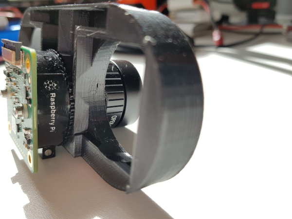
So, finally, all pieces come together in under the dome of the head part. The dome is dimming the picture a bit, so experiments will show whether computer vision works well enough. The manual focus of the Pi cam is helping here.

Eyes incl LED matrices and Pi Cam built into the head of the Omnibot 5402.

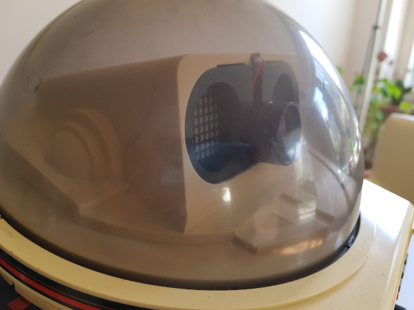
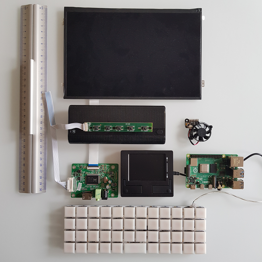
See the currently final setup here:

All parts of the current hardware setup in place. Now it’s a matter of software.

My first working mechanical keyboard

When designing little computers, one of the most interesting aspects is the dimension and functionality of the keyboard. Do you want to use it rarely and the screen real estate doesn’t matter? You can use an on screen keyboard. With little devices such as the PocketPi, it is okay to have a small keyboard, but that’s not for writing code, it’s okay for messages etc. Recently I bought a Psion Series 5 mx pro, that is a keyboard with 17cm length and a phantastic trade-off between usability and size. But I was also experimenting with self-built keyboards for a while and discovered that I’m not alone.

For building a sub-notebook or netbook powered by a Raspberry Pi, I was looking into 40% keyboards, my first experiment was a NIU PCB with Kailh Choc low profile switches just to find out that the NIU doesn’t support this form factor. I kind of hacked it by modifying the switches and soldering on the back side:

And it kind of worked. But it’s not beautiful and you have to mirror the default keyboard mapping. For my taste, the key caps are also too far apart, on the plus side, it has LEDs (the key caps are the “natural” color, i.e. semi-transparent which is also good for lights):

But then, after posting this on reddit, another forum member hinted that there would be the Pancake PCB that would “natively” support the low profile switches, so I ordered the pancake PCB together with the white key caps.

To save some more height, I decided to solder the Arduino Micro Pro directly on the PCB without a socket or pins, luckily, there’s also a QMK layout for it already and flashing with the QMK tool is a breeze (just press the button WHILE plugging in the USB cable to the computer).

That yields a total height of 18mm which is, in notebook terms, still quite a lot, but for mechanical keyboards it’s the best I can achieve for the moment.

The alternative would be to design and print a switch holder grid and connect the switches directly without a PCB. Whatever, this is the end result:

A much cleaner and tighter look compared to the NIU:

To learn how to type on an ortholinear keyboard, I practise on this sensational website. I was not very fast after 30min practise but improving fast:

So just as an outlook for the sub-notebook (10.1 inch screen, 21x15cm), here’s the hardware collection that I had half a year ago (yes, that’s a dedicated touchpad with mouse buttons in the middle). I’ll change the LiPo for a dual 18650 UPS I recently found which is way more compact.

absolutely fascinating organic display by ferrolic

here’s a liquid magnetic display by ferolic around a really bright guy named zelf koelman:

i was immediately fascinated by the organic movements of the drops and my brain couldn’t stop thinking about how to build one. we know magnetic particles from adaptive dampening in cars and we also know liquid displays as well as e-paper that turns pixels by a little magnetic current.

so this display is a combination of these and my feeling is that the display consists of little electro-magnets and some fluid that contains magnetic particles in oil. the trick has to be that these particles stay together.

i would guess that each pixel is one magnet that can be controlled individually, i thought this would be four seven segment digits with two mangets per line, i.e. 4x7x2 pixels = 56. then you also need some pixels to lift them from the soup at the bottom, for example 10 or so that would be 66. on the other hand you see that this is a full pixelated display, so if they are using 10×20 pixels, that would be 200.

first of all i did some research on the magnetic material called ferrofluid invented by NASA: “Ferrofluid was invented in 1963 by NASA’s Steve Papell as a liquid rocket fuel that could be drawn toward a pump inlet in a weightless environment by applying a magnetic field.” again, this interesting connection to my first association to the automotive application. it seems that these two materials are different in their properties due to their particle size though.

anyway. quick search on google yielded an article on instructables: 


interestingly, they also cite a project by martin frey in berlin:

next, we need some cheap and small electro-magnets, here are the cheapest & smallest, i could find on ebay:

two centimeters of diameter. i’m sure there’s something cheaper than 4.66€ because that would lead to 200×5 = 1000€ for the magnets.

finally, we need an arduino i would guess that either you use a nano with pwm per line, i.e. 10 ports, or a mega 20 pwms per column. finally, we need some shift register, for example this little guy: 74HC595, there is plenty of projects using it together with arduinos to drive LED matrix displays. for example this:


this would be a really nice project, would love to do it maybe during the christmas holidays. any further suggestions?