Walking robots are one of my favorites. There was a brave Korean gentleman that designed a simplified version of Boston Dynamics’ Spot mini, called the spot micro. I needed to build that:
When working on my version of the spotmicro, I noticed that the community is developing the gait patterns and inverse kinematics using simulators, here’s an example:
I’ve also read about pyBullet, Gazebo, MoJuCo but never was sure what they actually do and how deep they go, not only in terms of physics simulation but also for sensors / cameras as well as the learning of motor patterns or visual processing.
So I decided to take a little dive into that matter especially into pyBullet since it is a python wrappter / front end to Bullet. So you have a python script that loads the GUI as well as objects that are defined via links. These links can have motor functions. The motor functions can be controlled in the python script and thus also be computed by neural networks, state engines etc. Finally, you also have access to simulated sensors.
The nice thing is that you can really define the size and orientation as well as weight and other physical properties of the elements of the robot. The physics engine will then take care of computing the orientation and also collisions with other objects.
One way of defining the elements is using URDF, the Universal Robot Definition Format as defined by ROS, the Robot Operating System.
However, it was hard for me to find a simple example that was interesting enough to play with. Either the robots / objects were complex in definition or the python scripts were complex. This is why I collected some scripts and URDF files, simplified them to a very simple scenario that is interesting but also understandable in every file.
And I did my first publish on github! Clone the repository here:
The next important thing was to give the robot more personality and I found one or two chaps in the internet that worked on LED matrix eyes. But I also wanted to get computer vision to Omnibot so that it could see things or people and potentially speak to them, grab them or move towards them.
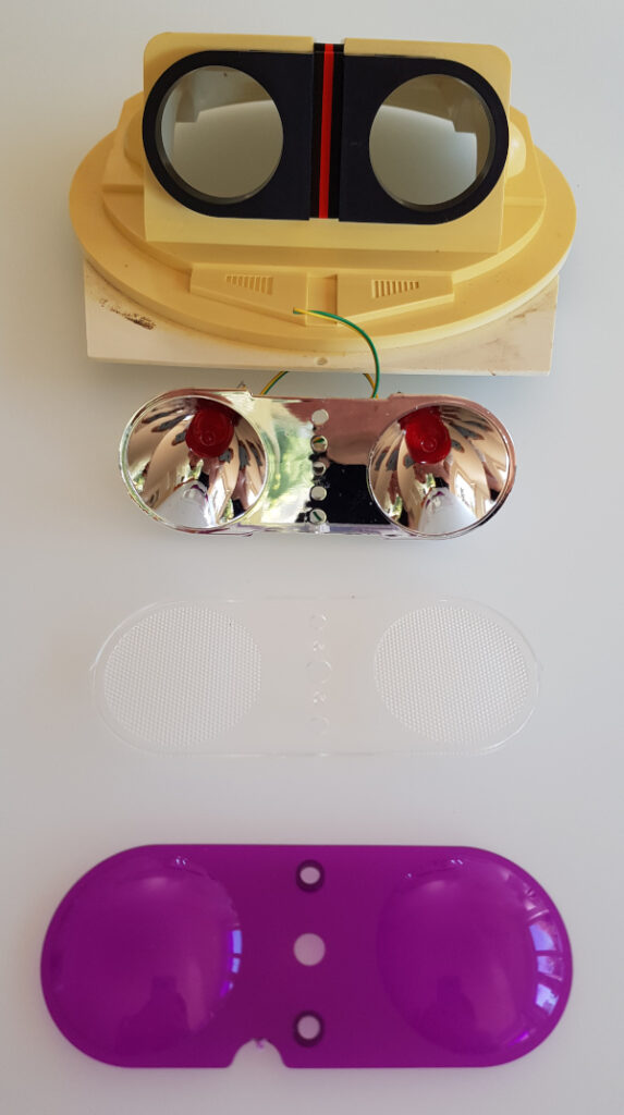
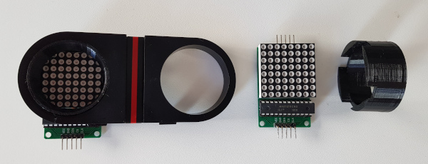
So let’s start with the decomposition of the original eyes which basically had a little lamp build in:
Omnibot 5402 head plate with reflectors, lamps, distortion plate and color filter
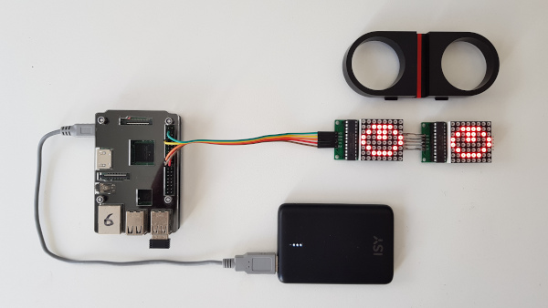
I decided to just keep the head plate and the black adapter and replace all other parts. Next I soldered the two 8×8 LED matrices, they are chainable and adapted the code from the above link.
Minimal expressive eyes (MEE) for the Omnibot 5402 powered by a Raspberry Pi 3.
This was very satisfying as there was a quick success. However, as you can see, the MAX7219 controller chip is standing out of the black adapter, making it impossible to build the eyes into the adapter. So the next iteration was to desolder them again and rotate them 90 degrees…
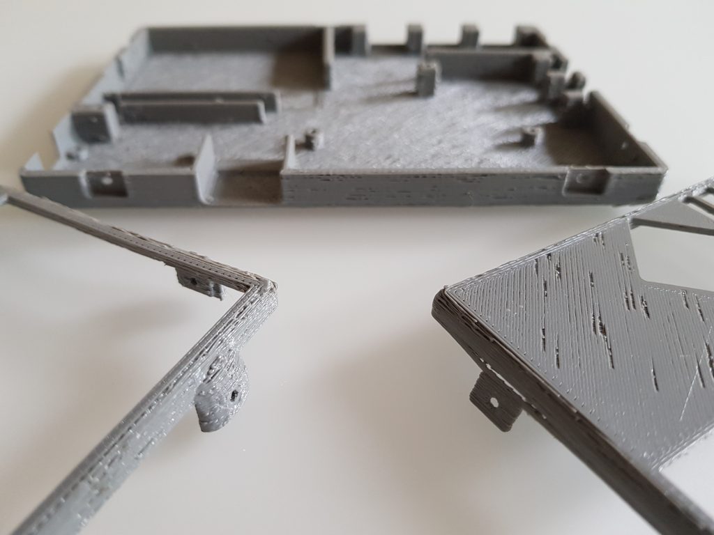
Rotated LED matrices and a 3d printed adapter from square to round.
I also decided to design a 3d printed adapter to keep the squared matrix in the round hole.
Original black Omnibot 5402 eye plate with black 3d printed adapters and the 8×8 LED matrices in place.
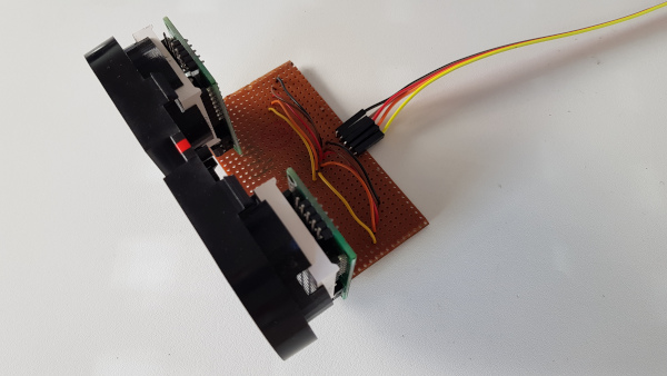
I also had to connect the two LED matrices differently as the pins would look downwards now. I decided to use a perf-board that I had in my cupboard from since my teenage years, so it would match the Omnibot in age 😀
Two LED matrices on perf-board and cable to the Raspberry Pi.
A little software experiment yielded this:
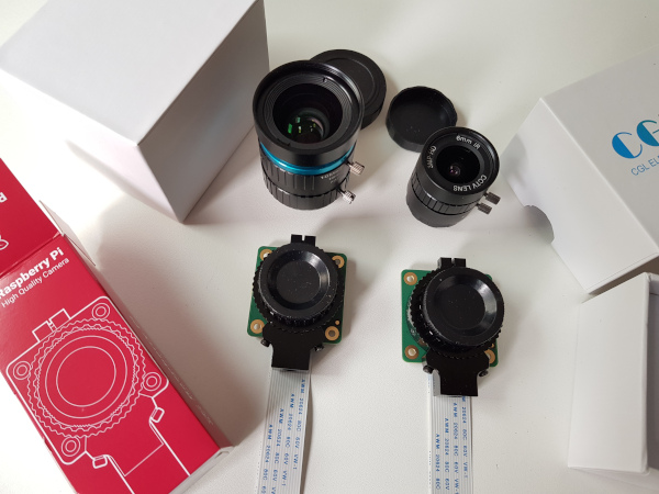
When I was working on the Omnibot’s eyes, the high resolution Raspberry Pi cameras were launched and I had to buy them immediately. I don’t really like the flimsy design on the original Pi cams.
The two objectives for the two 10 MP Raspberry Pi cams.
I decided to use the fish eye lens as it is small enough and would broaden the Field of View of the Omnibot.
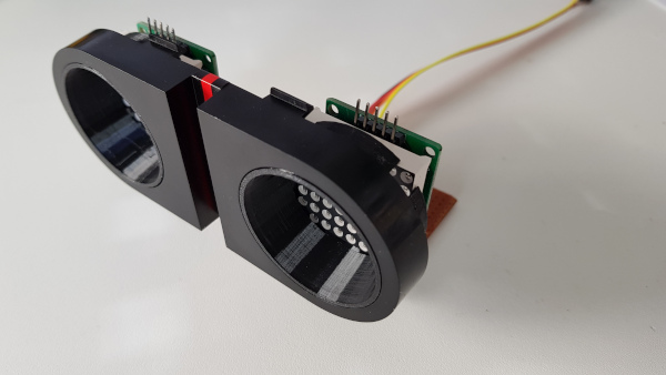
I realised that the original black Omnibot adapter certainly has no hole for the objective, but I definetly wanted to have the camera very close to the LED eyes. So I decided to do away with the adapter altogether and re-designed the whole adapter to keep the objective as well. This was not too easy as the diameter is really huge and I wanted to keep the matrices at a maximum in size.
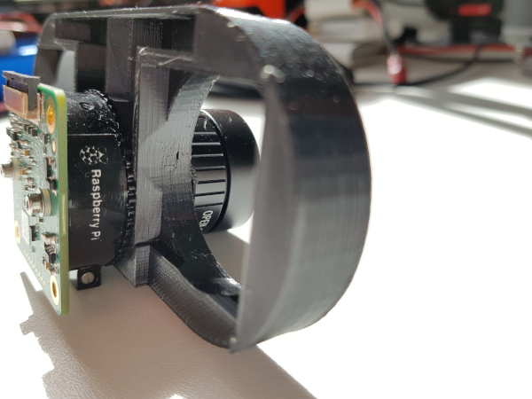
10 MP Raspberry Pi cam with fish eye lens in the next iteration of the Omnibot 5402 adapter.
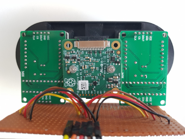
Finally, I also had to match the PCB with the matrix PCBs which also was not too easy. But luckily, it worked out:
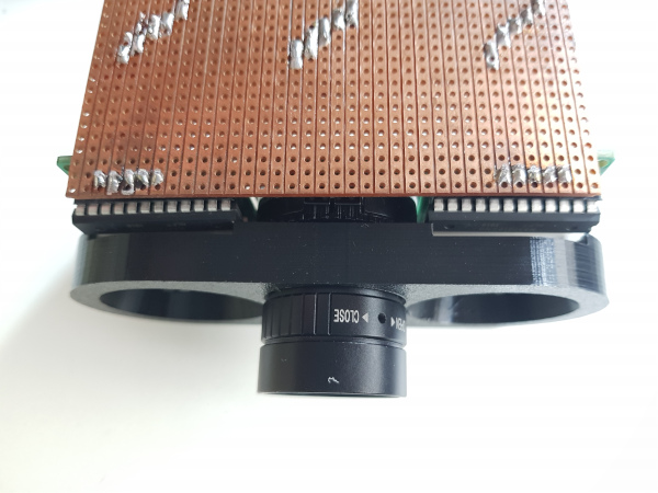
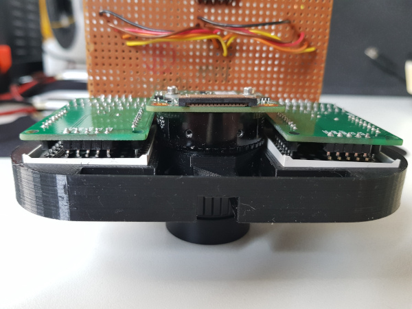
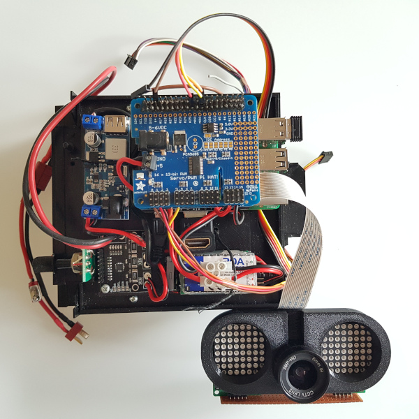
LED matrices, fish eye lens as well as all three PCBs in the 3d designed adapter.PCB view of the Omnibot 5402 eye adapter.Optimisation in height vs overlap was hard work.
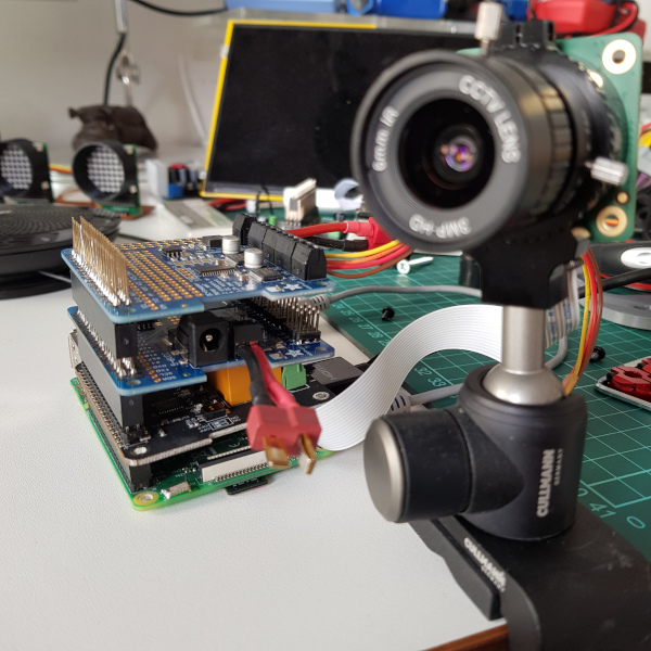
Finally, I had to buy a longer cable to connect the camera to the Raspberry Pi that was mounted on the Omnibot 5402’s tape recorder base plate in the meantime.
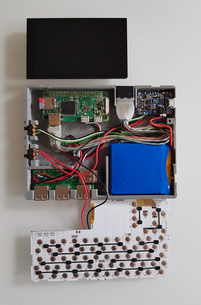
Hardware stack of the Omnibot 5402: Raspberry Pi 3, relais board to switch components, servo controller for the arms and motor control board for the wheels.Eyes adapter connected to the hardware stack including the power management: current sensor, bucket converter for the wheel motors and 5V bucket converter for the Raspberry Pi.
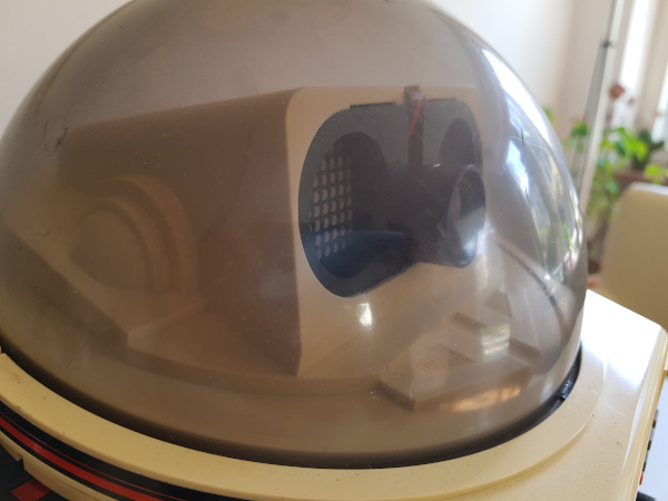
So, finally, all pieces come together in under the dome of the head part. The dome is dimming the picture a bit, so experiments will show whether computer vision works well enough. The manual focus of the Pi cam is helping here.
Eyes incl LED matrices and Pi Cam built into the head of the Omnibot 5402.
See the currently final setup here:
All parts of the current hardware setup in place. Now it’s a matter of software.
I always wanted the Omnibot to be able to actually grab and lift objects. So I started with the arms and recycled the 2 DoF shoulder servo pack from Trashbot.
The original two arms of the Omnibot 5402
The goal was to get the should parts replaced in a lean looking way. However, the original arms only move forward but not sideways, i.e. Omnibot cannot hug. Adding a second degree of freedom will thus inevitably broaden its shoulders:
Increaing distance between arm and body when using two servos
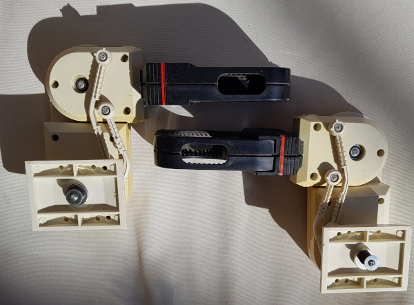
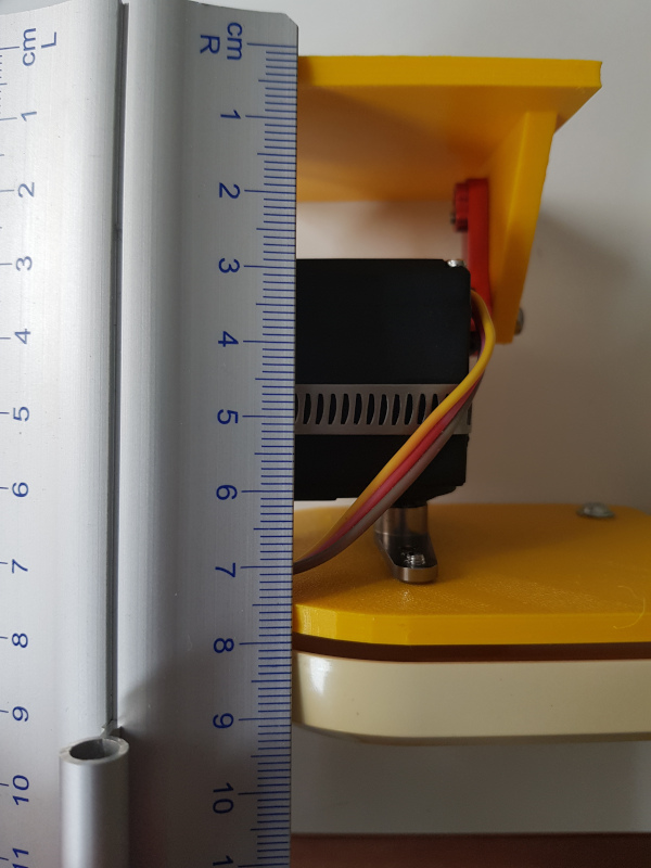
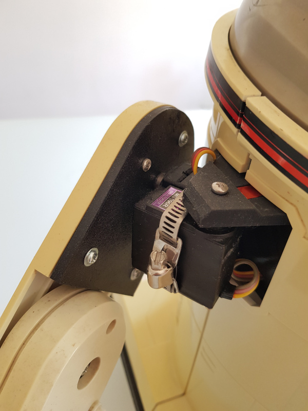
One trick was to hide the hugging servo within the body as good as possible. A next iteration could also hide the lifting servo a bit in the upper arm. For the current version, I chose to add it on a newly designed base plate that is at least slimmer than the inner should cover (compare it to the underarm):
Close up of the 3d printed 2 DoF shoulder joint on the Omnibot 5402
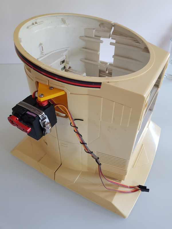
Here’s an earler version of the design, before I moved the should into the corpus:
Trashbot’s shoulders re-used in the Omnibot 5402
Software wise, I had to slow down the servo speed as otherwise Omnibot would move like this:
Single arm of the Omnibot 5402 moved by two servos without speed control
The final result are the two arms, each controlled by a thumbstick of the Bluetooth game controller. I added the Adafruit servo HAT to the stack that was using the motor stack before:
Omnibot 5402 moving two arms on two different axes using a bluetooth gaming controller
One of the things that are not making me happy is that Omnibot’s belly is to bold that it can’t close the arms and the arms are so short that they can’t lift anything that is in front of it. Fixing these two “bugs” would mean a complete redesign of the arms, I fear.
When i was a child, I was dreaming of the Omnibot 5402, I loved its size, its ability to be radio controlled, it could speak and it could record movements on a built-in tape recorder and it could carry things. A perfect companion!
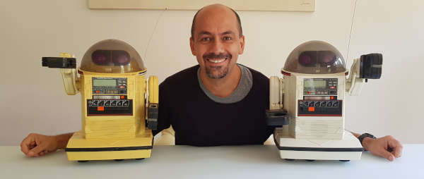
When you get older, you can make some of your youth dreams come true. So two years ago, I was lucky to get not only one, but two Omnibots on Ebay for 99$ (tax and shipping summed up to another 200$, though 😀 ):
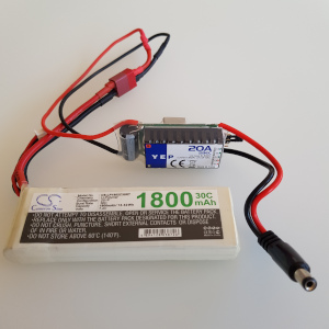
I cleaned the battery compartments of the remote control and the white one and made sure that these work properly, I replaced the original batteries with 2S 7.4V LiPos and bucket converters (max 20 Amps for the Omnibot itself):
1800mAh 7.4V LiPo and bucket converter and barrel connector for the Omnibot 5402
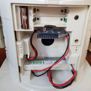
Battery and converter built into the Omnibot 5402
But the real fun starts with the yellow Omnibot:
I wanted to have a Raspberry Pi controlling it,
a decent Bluetooth remote control with more options,
the arms moving,
a camera for computer vision
USB sound card with a loud speaker and a microphone
LED matrix eyes for emotional expressions and to indicate where the robot’s looking at
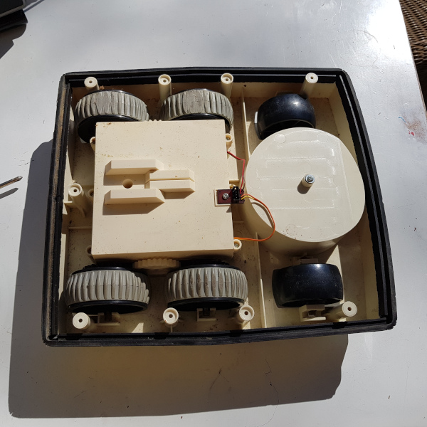
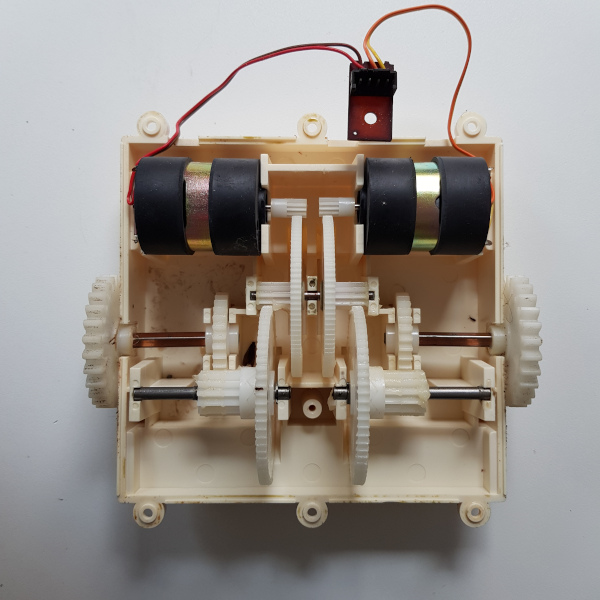
So, the journey starts with decomposing it and enjoying how it is constructed:
Base of the Omnibot 5402 including all wheels, gearbox and motors
That’s the lower part containing the four wheels that are driven by two motors in the gear box.
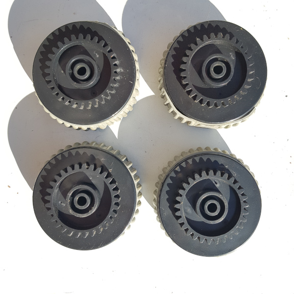
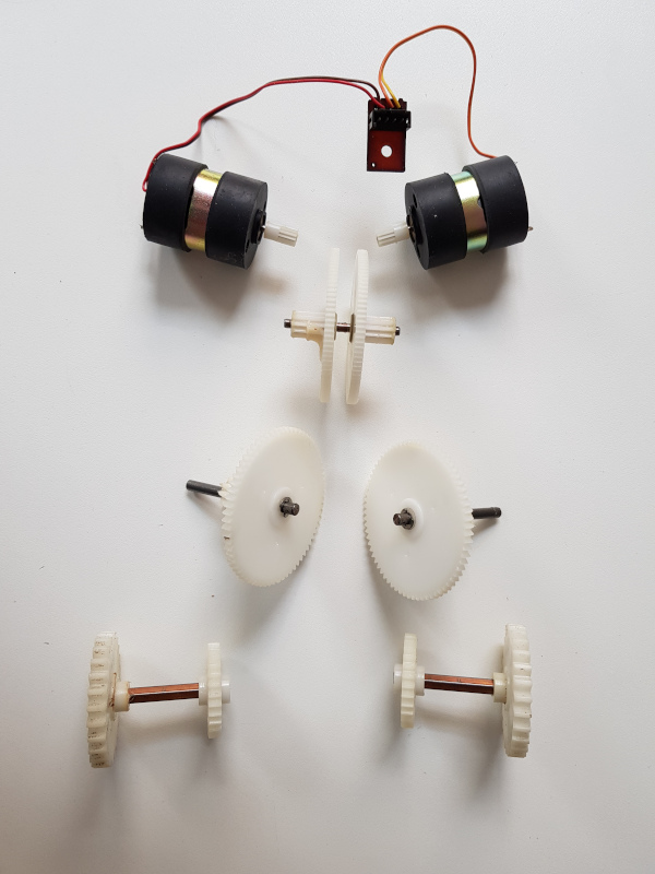
The four wheels of the Omnibot 5402, the belts light greay have flattened over the years.
Of course, we want to keep the robot as original as possible, so I needed a H-bridge controller to control these two motors.
Omnibot 5402 gearbox and motors openOmnibot 5402 gears taken out for cleaningOmnibot 5402 gearbox connected to the Adafruit Motorshield and the Raspberry Pi 3
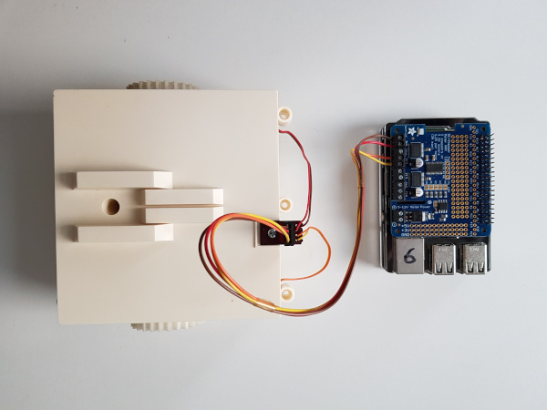
I took the original cable from the Omnibot’s motherboard and connected it to a Motor HAT from Adafruit. In that way, it was easy to use their examples to control the motors using Python.
Omnibot 5402 gearbox controlled by Raspberry Pi and Adafruit motor HAT
Next I’d build this into the base, add LiPo power to the motor controller and USB battery power to the Pi:
I decided to use the D-pad to control the Pi since I wanted to use the thumbsticks for the arms. The D-pad can be used to drive the Omnibot like a tank, forward lets both motors go forward, rotation on the spot can be achieved by turning the motors in opposite directions. Since the motor control is PWMed, we can also set the speed so that the speed is independent of the battery level.
I admit: I love how home computers from the 80ies were booting up in no time. I’ve been trying to optimise the boot up time for Raspberry Pis for some time but I don’t get very far. I’m also fascinated by baremetal implementations where hardware is used for a single purpose and also works on an instant. Micropython is a nice idea inbetween as it is a “high level language” and still runs without too much overhead on very small resources.
Another thing that I’m dreaming of is to be able to write software on the go using a minimal dedicated device. My prrevious attempts comprise:
The StickPi (super small Pi Zero with an epaper display and no keyboard for ssh access from a notebook, no battery)
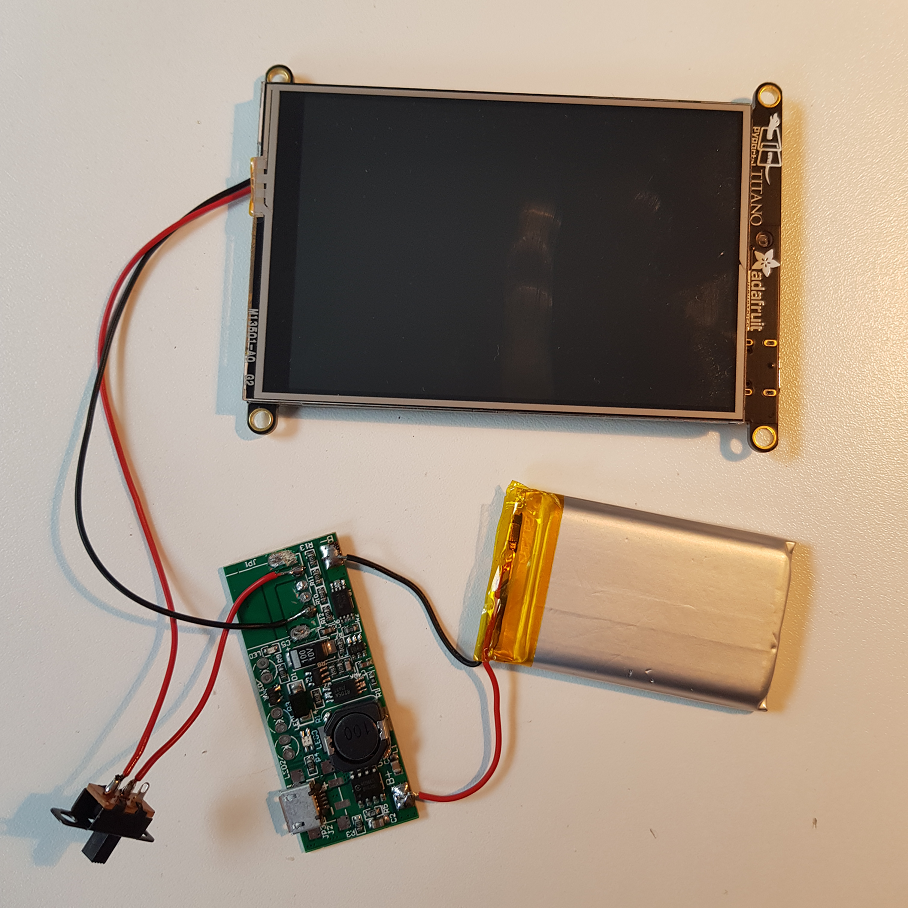
All these are Raspberry Pis in different formfactors. When the Adafruit PyPortal Titano was released, I was immediately in love as it comprises a lot of nice hardware and a 3.5in 320×480 screen that I also had evaluated for the PocketPi.
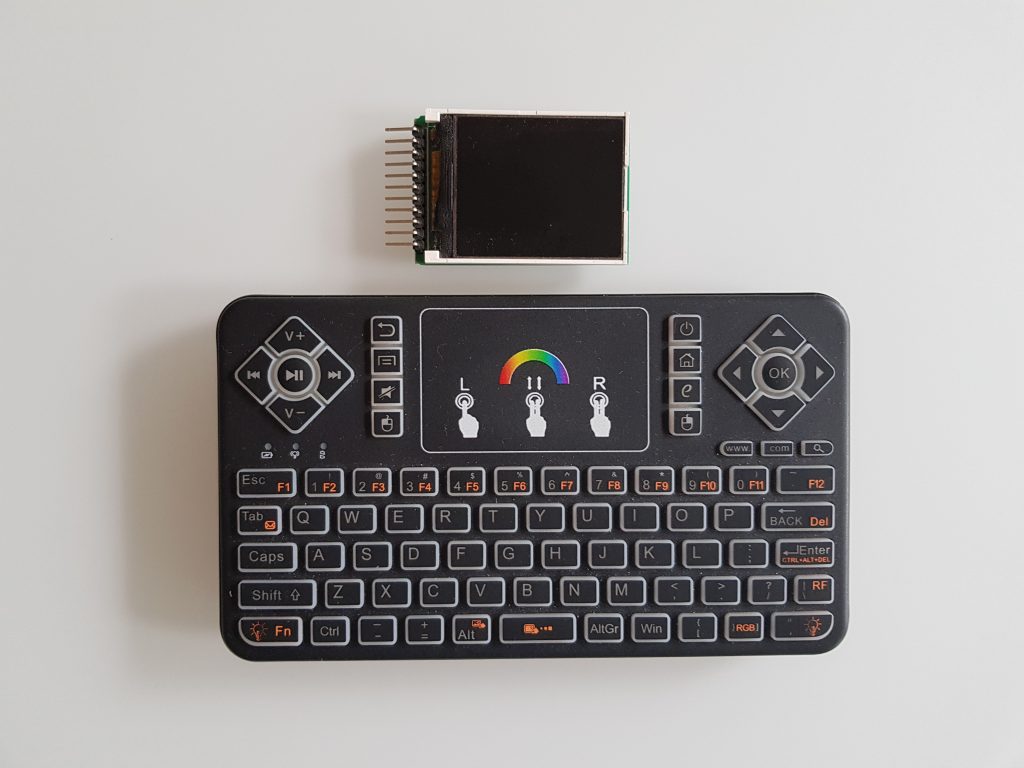
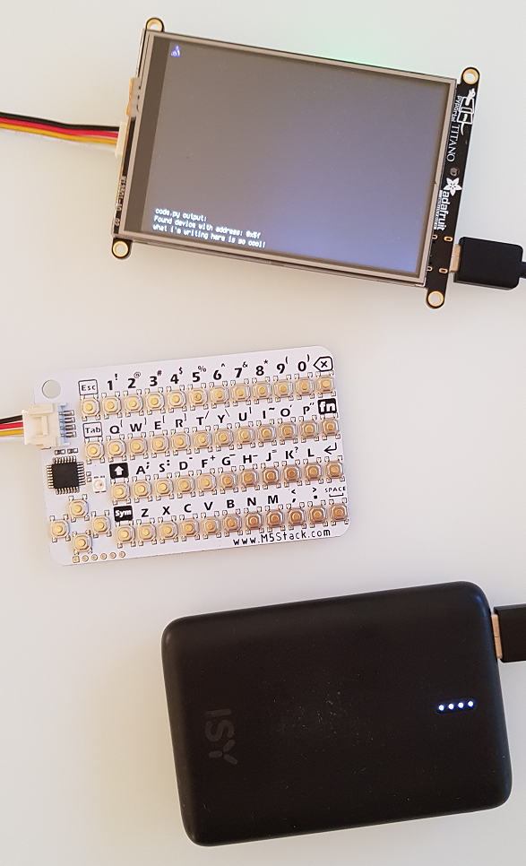
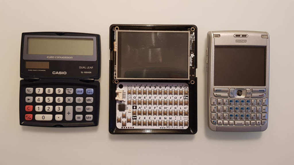
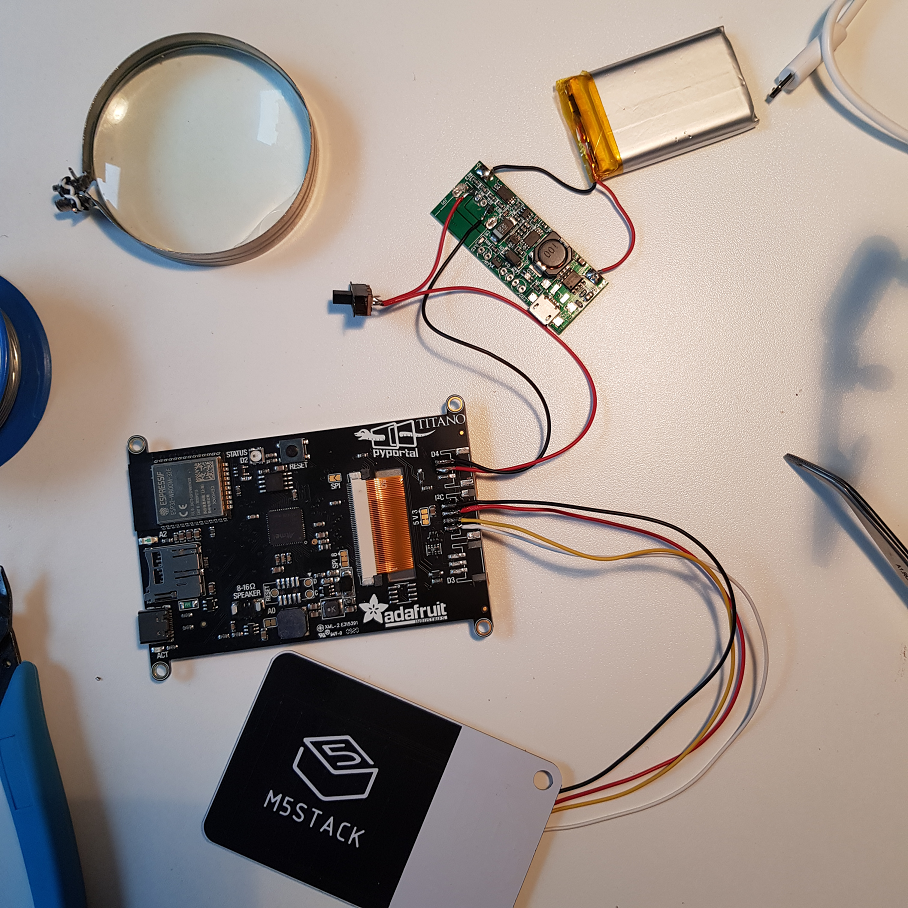
I also recently came across the hardware line of the M5Stack and their super-small and cheap I2C QWERTY keyboard caught my eye. The keyboard itself is also using an Arduino to read the key-matrix and translate the key presses to externally digestable code. So, this is my third Arduino-controlled keyboard (the recent mechanical keyboard and last week’s PsionPi). The PyPortal also has I2C connections, so let’s try it out:
So the first thing wanted to try out is to connect the two and see if I would get use the keyboard to enter text without a host computer or a USB keyboard. The keyboard is available at 0x5f and you just need to translate the keycodes to letters, certainly you need to translate delete, backspace and return keys to the right “actions” on screen, which kind of results in a minimalistic text editor:
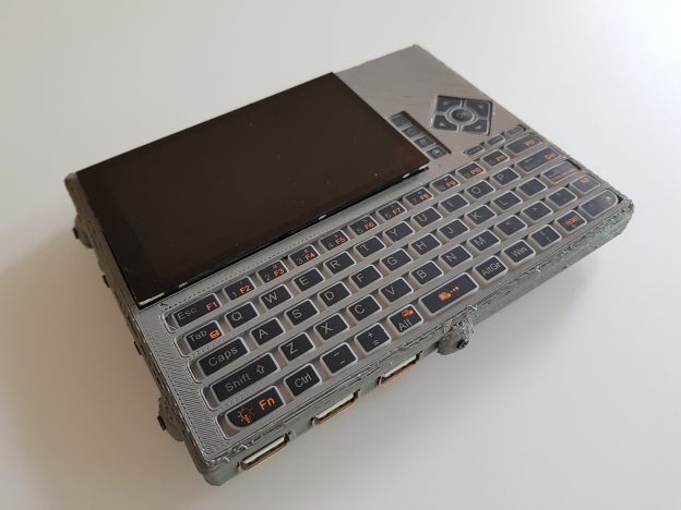
Next thing was to design a case. I never ventured into hinge design, so I wanted to keep it as simple as possible just to get started and to see whether writing code is fun or not. So I started with a slate design:
Actually, the Casio pocket calculator is a clamshell design already, but my beloved Nokia E61 is a good sparring partner in terms of design. So the black base plate is a 125x100mm design which is kind of nice, it wouldn’t get much smaller than this. I got bored with the slate immediately when it finished printing…
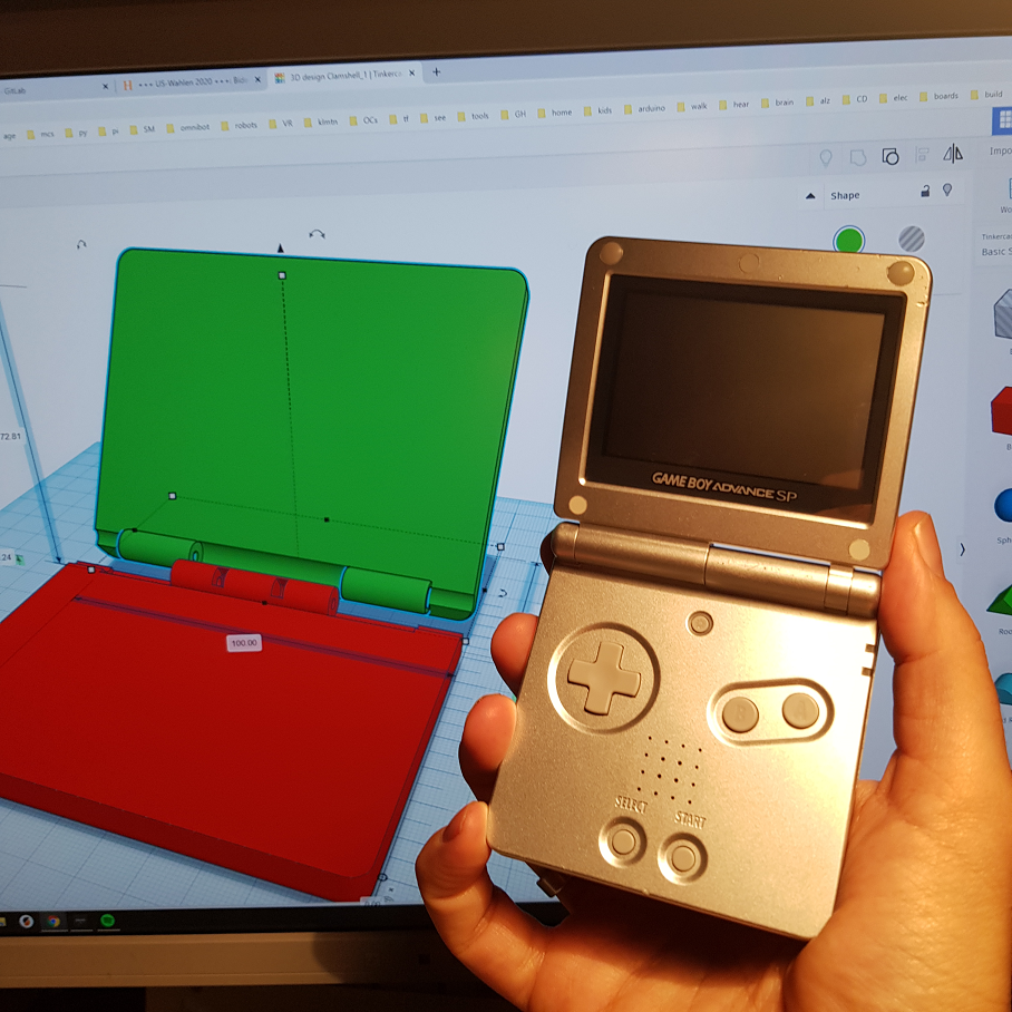
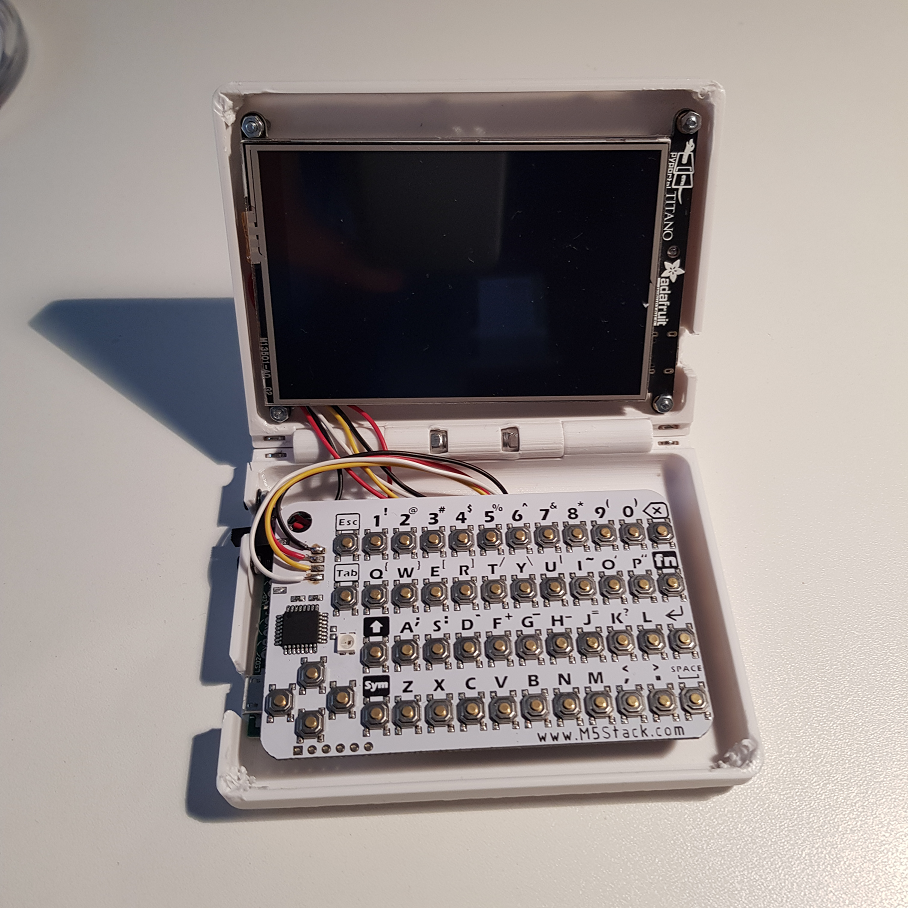
On the other hand, what was really a logical next step in terms of form factor was the clam shell design and when I had an old Gameboy Advance SP in my hand, I felt that I need this nice sound when closing and I wanted to have a computer like this. Back to Tinkercad:
Now the baseplate has 100x80mm and the hinge is working really well. I also added magnets on all corners to keep the states stable but they are not strong enough and take up valuable space.
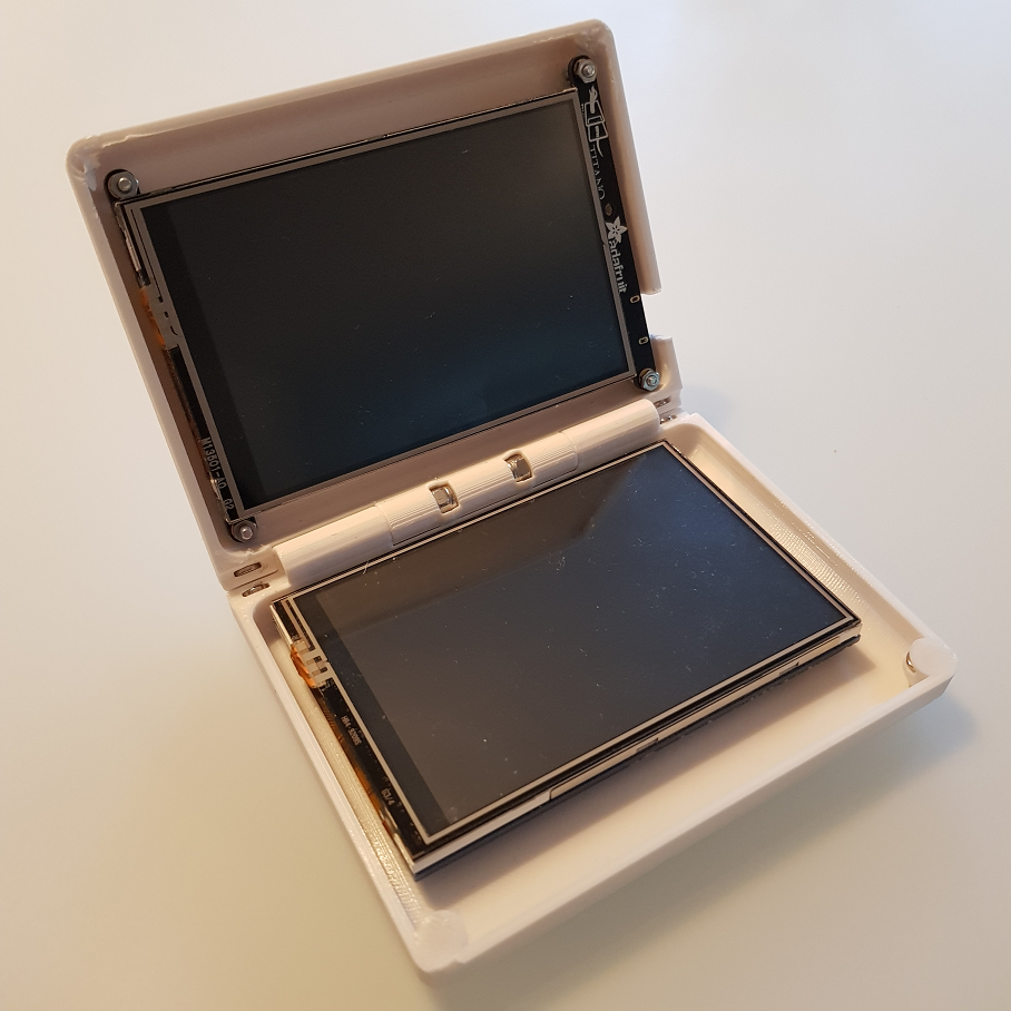
Just for fun, I pulled out my old screen from the earlier PocketPi iterations:
To make this usable, you’d need to add the Pi Zero underneath and power both with a battery plus connect them somehow (not via Wifi 😀 ).
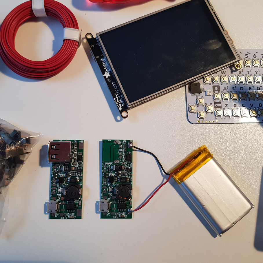
Next it was time to design the power source. This time I didn’t stick with the Adafruit powerboost, I think it is too expensive and it gets fairly hot. I had a couple of cheaper but larger charger boards in a drawer, so I decided to give them a go. To save height and space, I removed the USB plug:
To save height, I also removes the plugs from the pyportal and wired the power cable directly, following the wiring scheme from Adafruit:
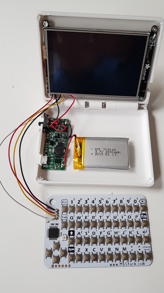
Finally, I also removed the plug from the M5Stack keyboard and soldered the cable directly:
I had to modify a couple of places of the original case design and cut out the plugs for USB-C / pyportal, the power switch and the micro-USB charging port, then it was time to fit the power circuit:
Finally, the keyboard is added using a double-sided tape:
And now the little darling in action:
I wrote a little file lister in python as well as a minimalistic python editor. The problem at the moment is that you can’t write to the on-board flash when hooked up to a host using USB-C. Need to check out now whether it works when the device is battery powered. Stay tuned!
UPDATE: I just polished the case design to actually close properly and removed the magnet holders to give the innards enough space. Files are published on Thingiverse now.
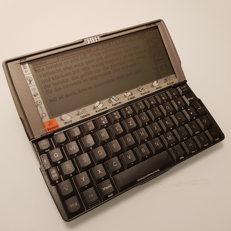
There’s certainly an emotional connection to EPOC, the precursor of Symbian OS that was running the high end devices of NOKIA a decade ago. EPOC was initially developed by PSION who kind of pioneered mobile computing (at least here in Europe) with decent keyboards.
Whenever you research about mobile computing all aficiandos praise the quality of the PSION keyboards. Especially the 5 Series are great – so I heard.
But when you look at the device, there is so much love to detail and passion in the design, for example see the hinge:
Actually, I want to build a little computer to write Python programs on the go. My experience with my previous, smaller design, the PocketPi, was that it is actually to small (keyboard and screenwise) to really write code and think about it.
The PSION keyboard is really nice and the 6inch screen is kind of nice, too. There’s even a Python port for this granddad. But I decided to build my own little device, so a Raspberry Pi would be the right computing platform.
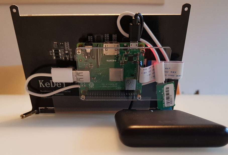
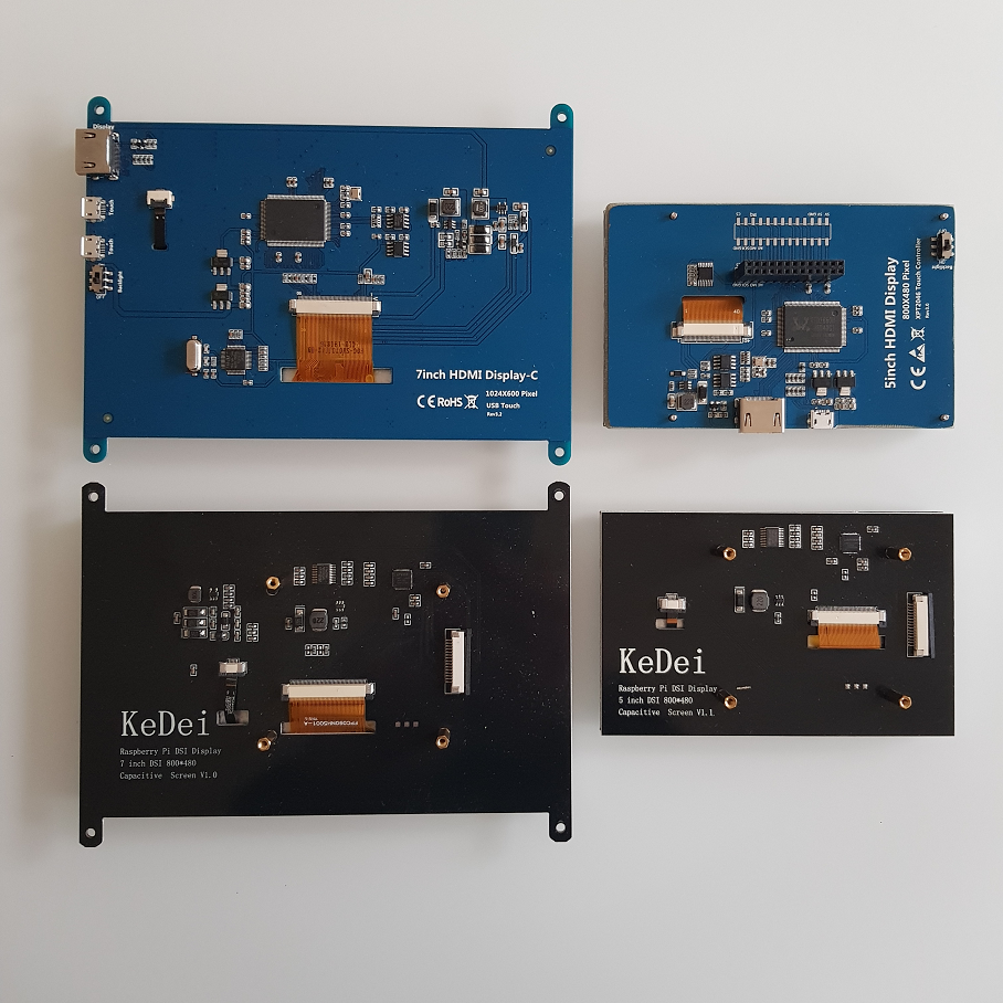
Recently, some new displays are available on the market that save the whole HDMI cables and possible additional screen controller boards. These connect directly via a flat cable to the onboard DSI screen interface of Raspberry Pis. This saves a lot of space an height.
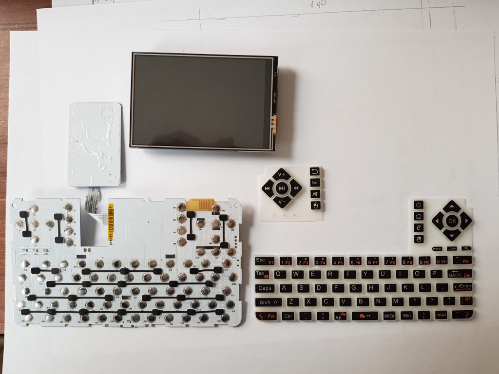
You see the USB and HDMI plugs on the left of the 7in screen, missing on the lower screens, these have the flat cable plugs on the board on the right hand side. So for this build, I used the 7in DSI screen that also includes capacitive touch (60€, 800×480 resolution). Both, display and touch functionality are supported by the OS out of the box.
Finally, I also bought a series 5 keyboard on ebay because I wasn’t able to slaughter the functional one that I bought before. There is a guy who tried to fit a Raspberry Pi into the original series 5 case, but he didn’t get very far. What he achieved however, is to design a little PCB containing an Arduino 32U4 (Leonardo compatible) that translates the keyboard’s signals to a USB-HID keyboard profile. It’s about 40€ (adding to the 90€ I paid for the keyboard and the screen).
Finally I chose the Raspberry Pi 3a+ that has runs on a 1.4Ghz quadcore ARM and includes Wifi and Bluetooth. I love that device because it doesn’t have to many plugs (like LAN or quad-USB like the Pi4), so it’s flat and light. It also includes the DSI port while the Pi Zero W doesn’t.
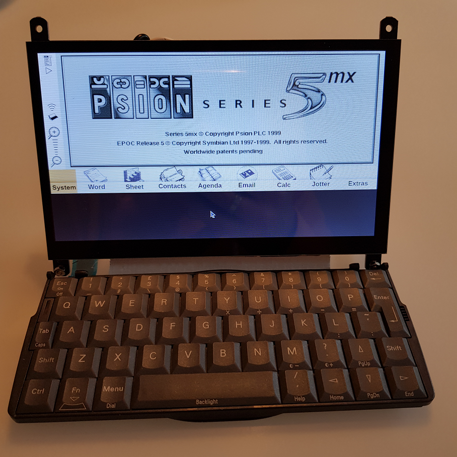
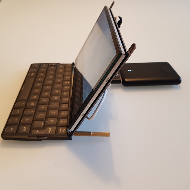
So this is the final “build” (or rather “composition”, I used a gaffer tape to attac the keyboard to the screen):
So, while the screen itself is about 10mm thick, the Pi 3a adds another 20mm, which is totally unacceptable, esp compared to the Series 5 original 25mm. The screen incl the screw holes is about 120mm, while the keyboard is about 75mm. The Pi 3a+ has 55mm, so if I design a case, maybe I’d move the Pi to the keyboard and would get a floor of 130mm plus case walls. Not sure yet. Probably will also research a different screen, with OLED these are much thinner and lighter.
Software wise, I had to flash the keyboard with an Arduino script provided by the controller board guy on Tindie. That was easy, but it doesn’t support QMK like the pancake 40% mechanical keyboard I built last week. Doesn’t matter, the mapping is easy enough to change in the source code.
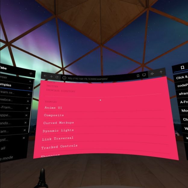
Finally, firing up the system and now the EPOC OS. For the first test, I used the emulation running in the browser. On a PC it boots like in a second, on the Pi 3a+ it takes about five minutes, so this is not an option. But see here:
When designing little computers, one of the most interesting aspects is the dimension and functionality of the keyboard. Do you want to use it rarely and the screen real estate doesn’t matter? You can use an on screen keyboard. With little devices such as the PocketPi, it is okay to have a small keyboard, but that’s not for writing code, it’s okay for messages etc. Recently I bought a Psion Series 5 mx pro, that is a keyboard with 17cm length and a phantastic trade-off between usability and size. But I was also experimenting with self-built keyboards for a while and discovered that I’m not alone.
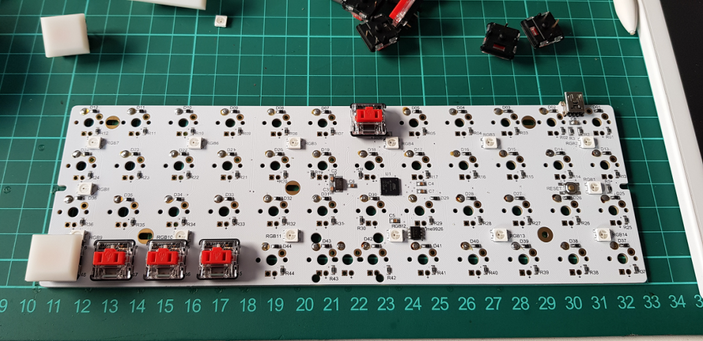
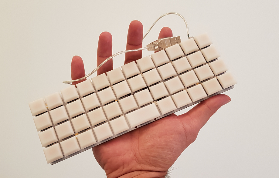
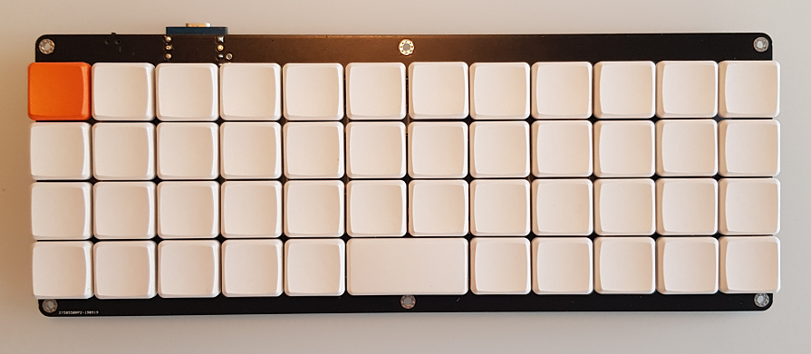
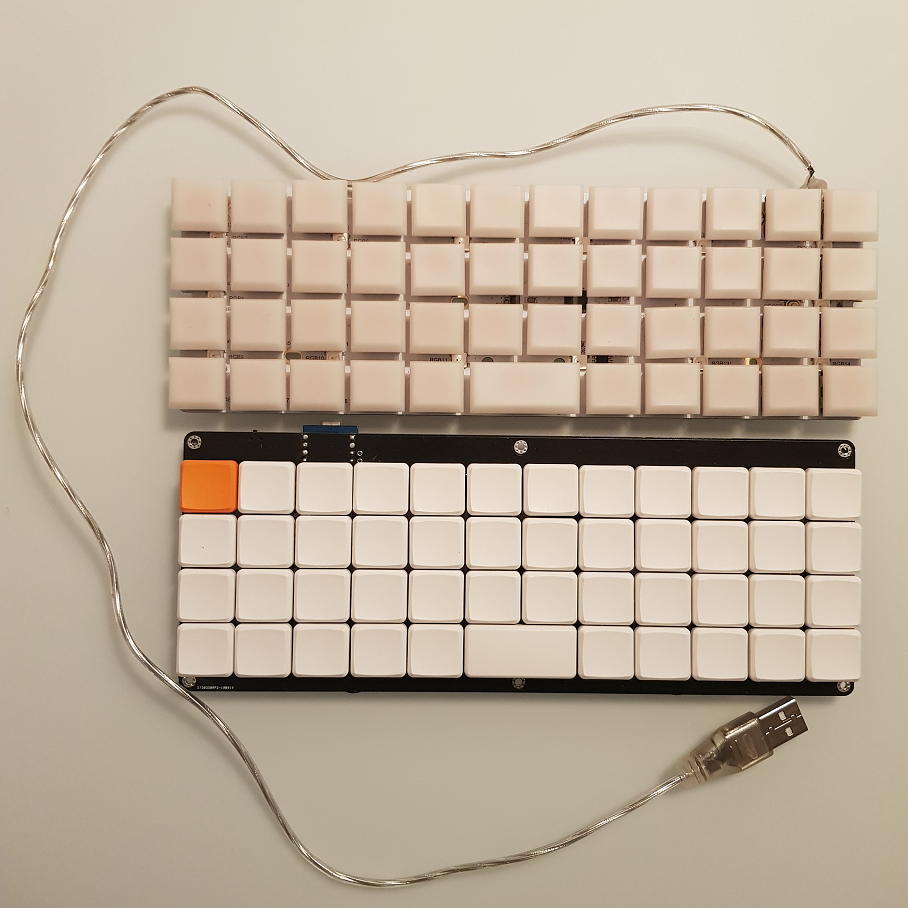
For building a sub-notebook or netbook powered by a Raspberry Pi, I was looking into 40% keyboards, my first experiment was a NIU PCB with Kailh Choc low profile switches just to find out that the NIU doesn’t support this form factor. I kind of hacked it by modifying the switches and soldering on the back side:
And it kind of worked. But it’s not beautiful and you have to mirror the default keyboard mapping. For my taste, the key caps are also too far apart, on the plus side, it has LEDs (the key caps are the “natural” color, i.e. semi-transparent which is also good for lights):
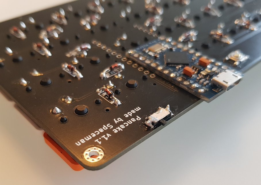
To save some more height, I decided to solder the Arduino Micro Pro directly on the PCB without a socket or pins, luckily, there’s also a QMK layout for it already and flashing with the QMK tool is a breeze (just press the button WHILE plugging in the USB cable to the computer).
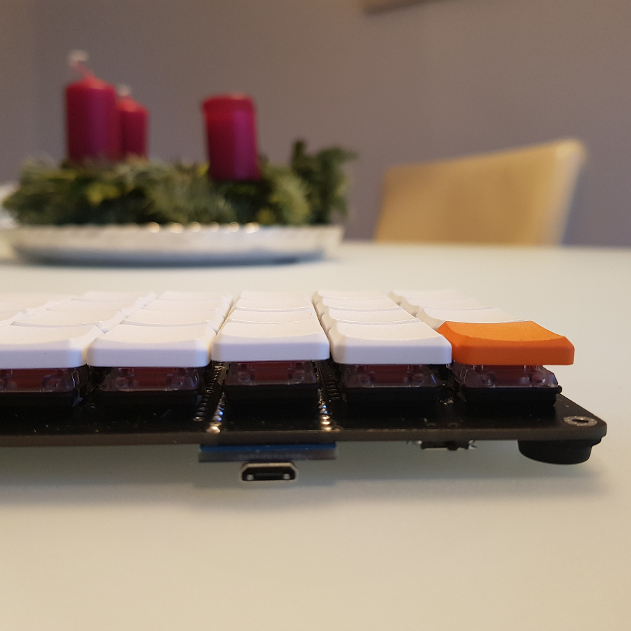
That yields a total height of 18mm which is, in notebook terms, still quite a lot, but for mechanical keyboards it’s the best I can achieve for the moment.
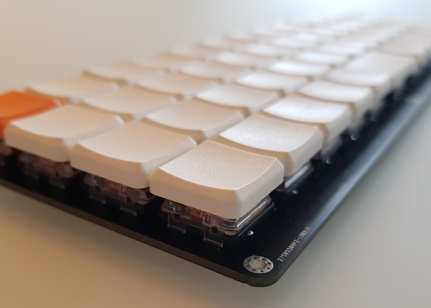
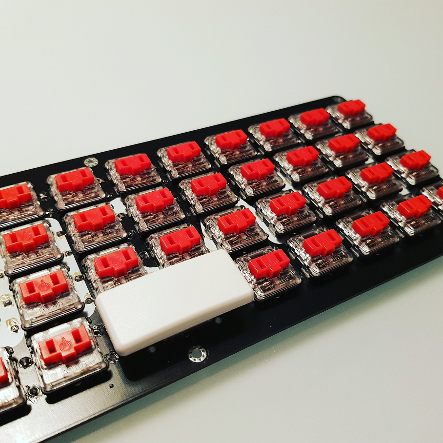
The alternative would be to design and print a switch holder grid and connect the switches directly without a PCB. Whatever, this is the end result:
A much cleaner and tighter look compared to the NIU:
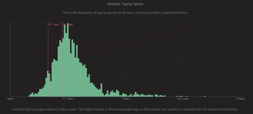
To learn how to type on an ortholinear keyboard, I practise on this sensational website. I was not very fast after 30min practise but improving fast:
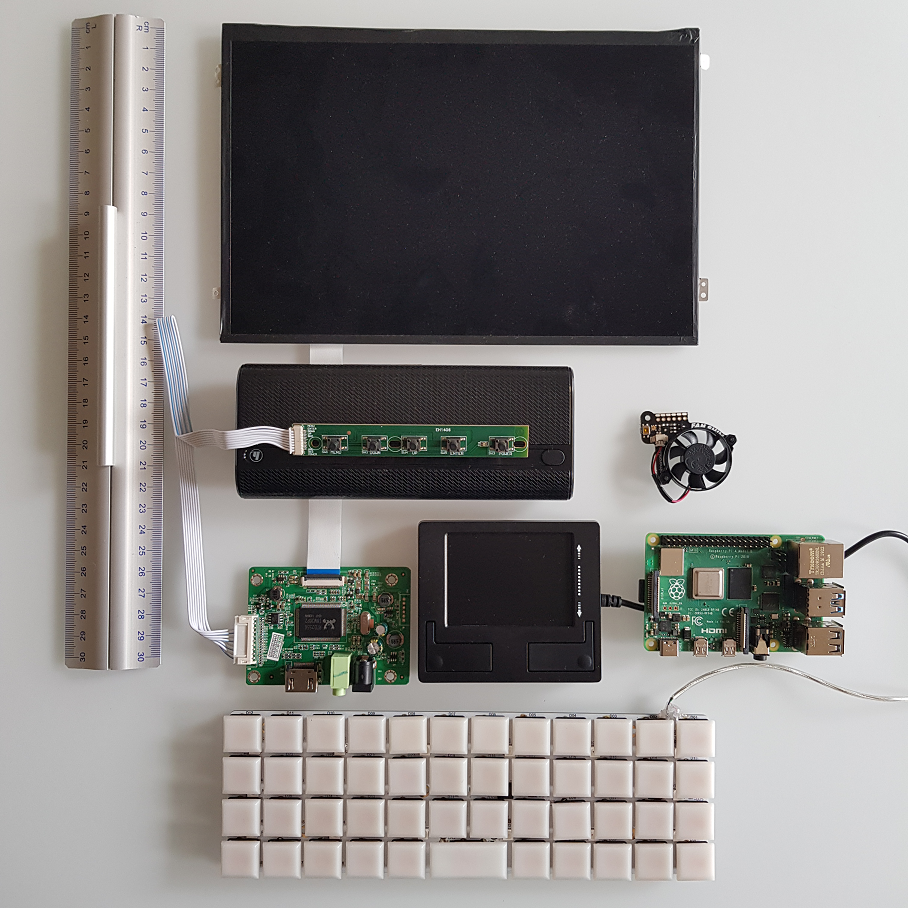
So just as an outlook for the sub-notebook (10.1 inch screen, 21x15cm), here’s the hardware collection that I had half a year ago (yes, that’s a dedicated touchpad with mouse buttons in the middle). I’ll change the LiPo for a dual 18650 UPS I recently found which is way more compact.
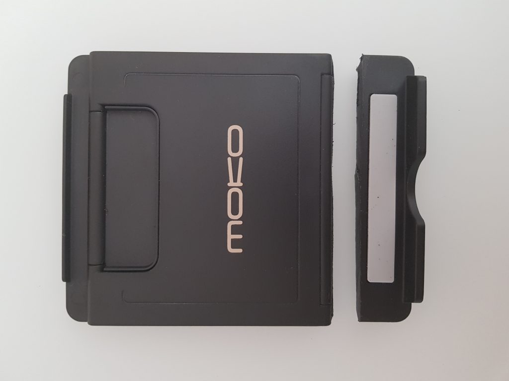
This is my first Chromebook and I really love it as it’s ARM driven, has Android support and runs Linux in a VM. The only thing I don’t like is the original kickstand that comes with it as it weighs 240g.
So I ordered this 46g foldable tablet stand and removed the lower lip that usually holds the tablet in place. For the chrombook I need a direct connection to the keyboard that is a broad cloth-like connection to the tablet part.
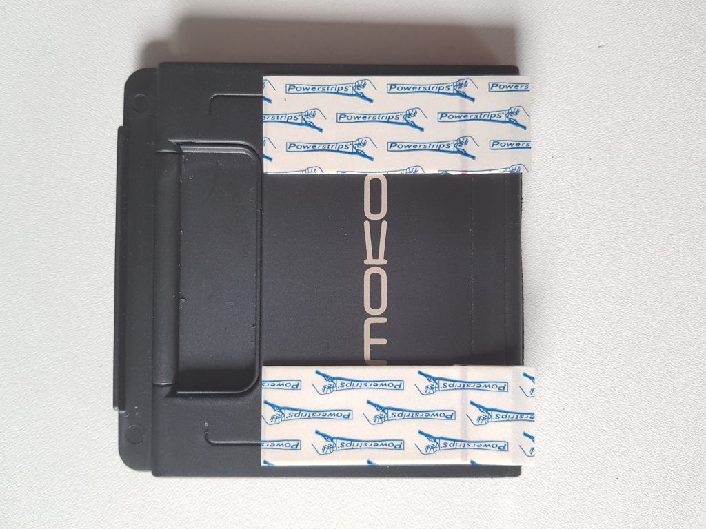
As this is an experiment, I added “power strips” to it, which is a two-sided glue tape that you can remove easily without leaving stains behind.
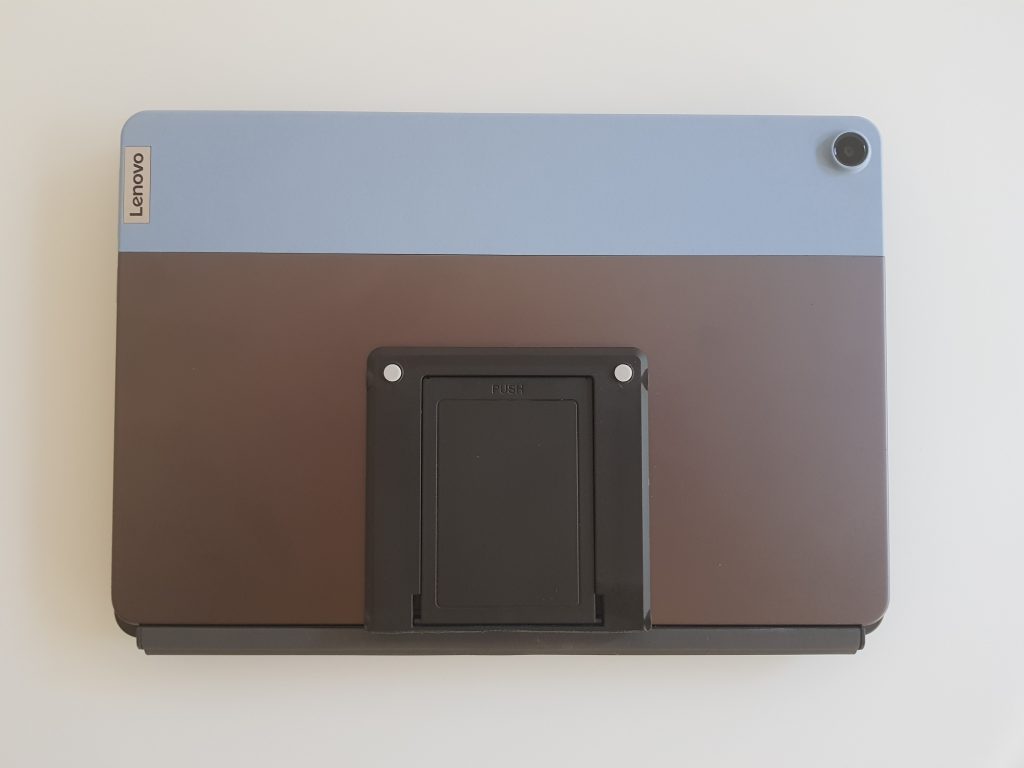
Finally, I placed it in the middle of the tablet part:
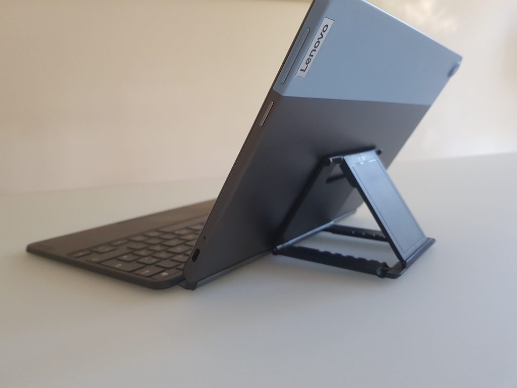
And voilá, this is how it looks like:
I may design something similar in 3d with even flatter angles and more rounded edges when folded so that I can put it into a bag without the risk of tangling.
Short-cut: for instructions how to run a server on the Quest for developing a-frame webVR apps that run on the Quest, scroll down to how-to:
Background: Reading William Gibson’s Neuromancer as a child, I was always intrigued by how to get, stay and work in “the matrix” / cyberspace. Today, VR is still not where Gibson conceptualised it (we don’t have meaningful and conventionalised data visualisation and navigation in 3d yet), but still we’re making baby steps. When I first saw this video in 2014, I fell in love with the idea to write live updating code in VR:
Inspecting the code today, it isn’t built in a-frame or webVR as far as I understand, but in threeJS which afaik underlies webVR. It’s not hosted anywhere anymore, so you can’t try it out on your headset.
Although, having owned the DK2 and the CV1, the Oculus Quest finally is the device of my dreams as it doesn’t depend on external sensor setups, cables or a PC. For the moment, I don’t care about the resolution and the GPU. I want to explore the idea of having a fully fledged computer on your body to work with. It’s really a new device category. Right now, content and software is developed outside HMD and then tested on them (think Unity 3d etc), even for phones, this is the case, you can’t develop for Android in Android without anything else (at least last time I checked). From my perspective (I grew up with the Commodore C64), the computer to consume on should be the computer to produce on.
The Quest is a computer, it has a huge screen, it has an OS, internet connection, it runs Android and is bluetooth capable. I came across a-frame and think that for the moment, this is the go-to development framework compared to Unity 3d et al. However, to develop for a-frame, you also need a web-server (although systems like glitch.me and pencode allow you to work in the browser). Thus, ideally this server itself should also run on the Quest (my ideal is self-contained).
Keyboard: I successfully paired a bluetooth keyboard (using a sideloaded bt lister app, this one works on the Quest, others didn’t) and it works in the Oculus Browser but not in the (side loaded) Firefox Reality browser (current version in Beta: 1.2.3, use *oculusvr-arm64-release-signed-aligned.apk for the Oculus Quest, start it from “unknown sources”). It also works in termux (see below).
[Optional: I successfully can work in glitch in the Oculus Quest browser (here’s something I composed from two other glitches plus some of my own code: https://glitch.com/~gallery-appear-disappear use grip button on all the objects, triceratops will produce boxes with physics, sphere will change environment, resize the picture using both controllers). Note: You can leave out this step but it’s nice to see that you can work on code in a VR browser and experience it in the same browser.]
I successfully sideloaded termUX (it “contains” / “makes accessible” Linux in Android and interfaces with the hardware, read here) and can run it in the OculusTV environment (bigger screensize would be nice though).
In termUX (keep it up to date by issueing: apt-get update and apt-get upgrade), we should install:
pkg install nano (cmdline texteditor)
pkg install python (in some cases needed
pkg install nodejs (node js and npm)
pkg install git (for pulling git repositories)
Next, we install a-frame by issueing git clone https://github.com/aframevr/aframe.git and change to that directory
We install the package by npm install
And we start npm start
It takes a while for the system to put together the server and start it, finally it will print something like “server started at http://192.168.178.xx:9000”, call that from your Oculus Browser (or Firefox Reality) and voilá:
Certainly, it is still a bit cumbersome to change between termUX (that is to be called via OculusTV) and the browser and yes, nano is not the perfect tool to work on java script and HTML, BUT: we have it working! A self-contained system running on the Oculus Quest for developing a-frame / webVR applications.
I was able to connect a webcam using OTG with my phone and found an app in the Google Playstore that actually can stream video on the phone’s screen. But sideloading it to the Quest and starting it there doesn’t deliver a live stream. Intention is to look at my keyboard in VR)
I found some webVR code that can use the webcam as texture on an object. It works on my PC but not on the Quest (neither Oculus Browser nor the Firefox Reality although the latter has an enable button for webcams)
I installed OVRVNC to login to my Raspberry Pi, connect a webcam to that and stream video from there and run a webserver. However, on the Quest it doesn’t connect to my Pi VNC session from a PC works.
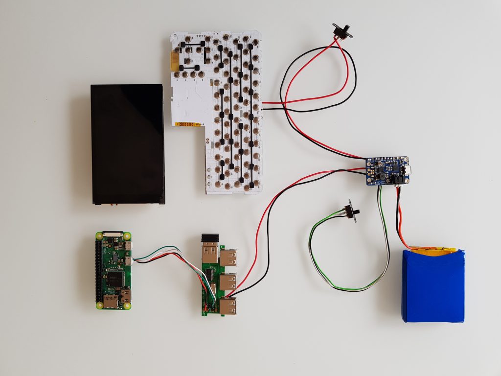
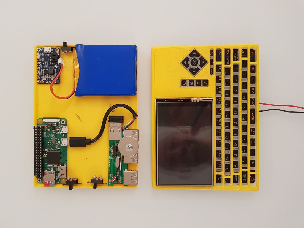
TL;DR: 14x11cm portable Raspberry Pi Zero W with 3000mAh Adafruit powerboost 1000, Hyperpixel 4inch display, a keyboard and a4 port USB hub. Scroll down for videos, STL files, shopping list.
I always want to be able to carry a little computer around that reduces the outside distractions, like no email, ideally no browser, no messaging, etc. Actually, I enjoy the “silence” that I have with the Raspberry Pis. They allow me to focus on writing software for robots and the like.
Sometimes, you want to code on the go. My second shot in that direction is the StickPi, a little computer without battery but with an e-paper display and a couple of buttons. I actually keep using it, it’s my most used self designed computer.
My first shot hasn’t been published yet: the SlatePi. It is a 5inch computer with a small keyboard and a 4000mA battery, but it seems to be to large for every day use.
So I did another computer: today’s PocketPi. It is the symbiosis of the first two: portable but still a full keybard and a battery included.
It all started with the idea to build a Pi Zero and a display into my favorite mobile keyboard:
I wanted to replace the mousepad with that display.
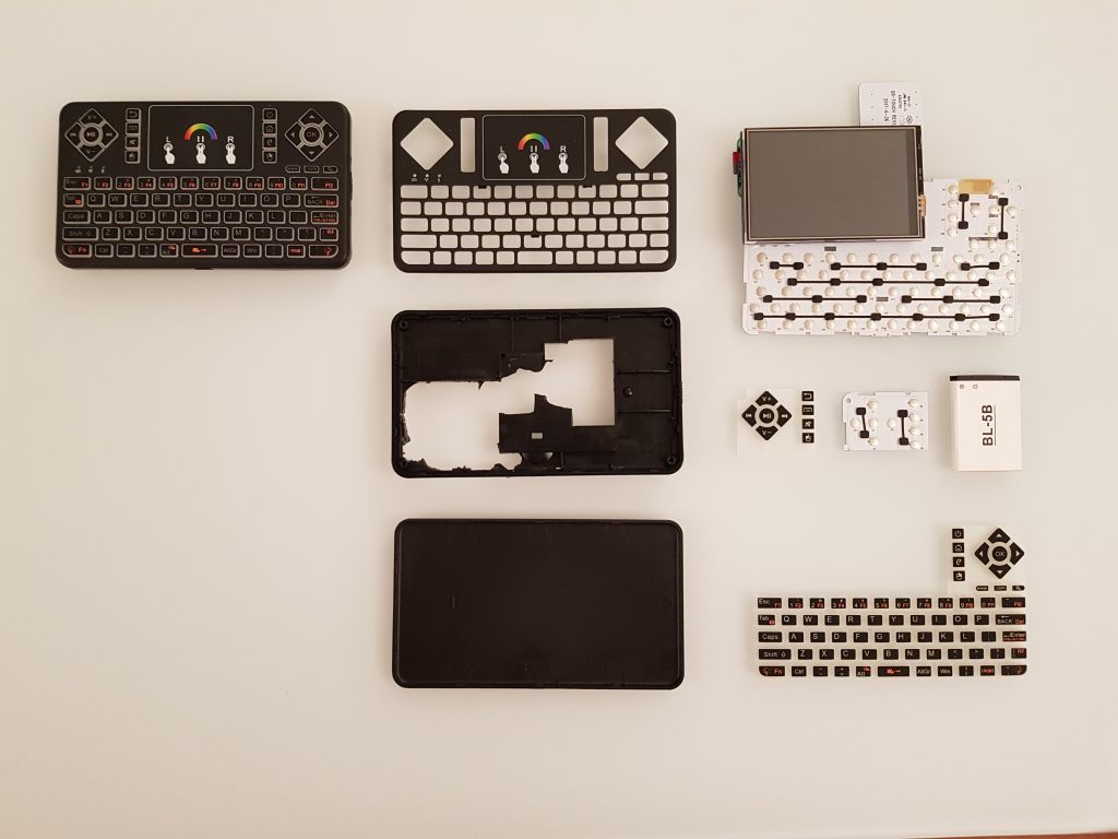
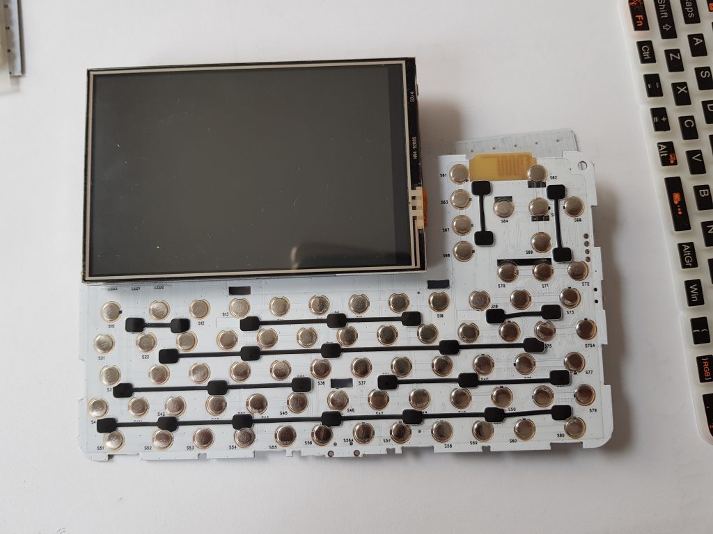
So at some time, I started to decompose that keyboard to understand how much space is there to actually fit in a Pi Zero W, battery and the display.
the decomposed keyboard and already cut off left part of the PCB and softkeys.
I quickly learned that a) the inclusion of the driver for a ST7735 1.8inch display is cumbersome and the resolution might actually not be nice for really working with it (128×160), it may be better suited for a retroPi machine.
So I decided to use another display that I had at home already which is a 3.5inch display for the Pi (without HDMI) and some more decent 480×320 resolution.
[I also removed the original battery plug and the keyboard’s switch to reduce height.]
However, I didn’t want to increase the size of the device by the height of the diplay and thus decided that I don’t need the left (media-related) buttons of the keyboard:
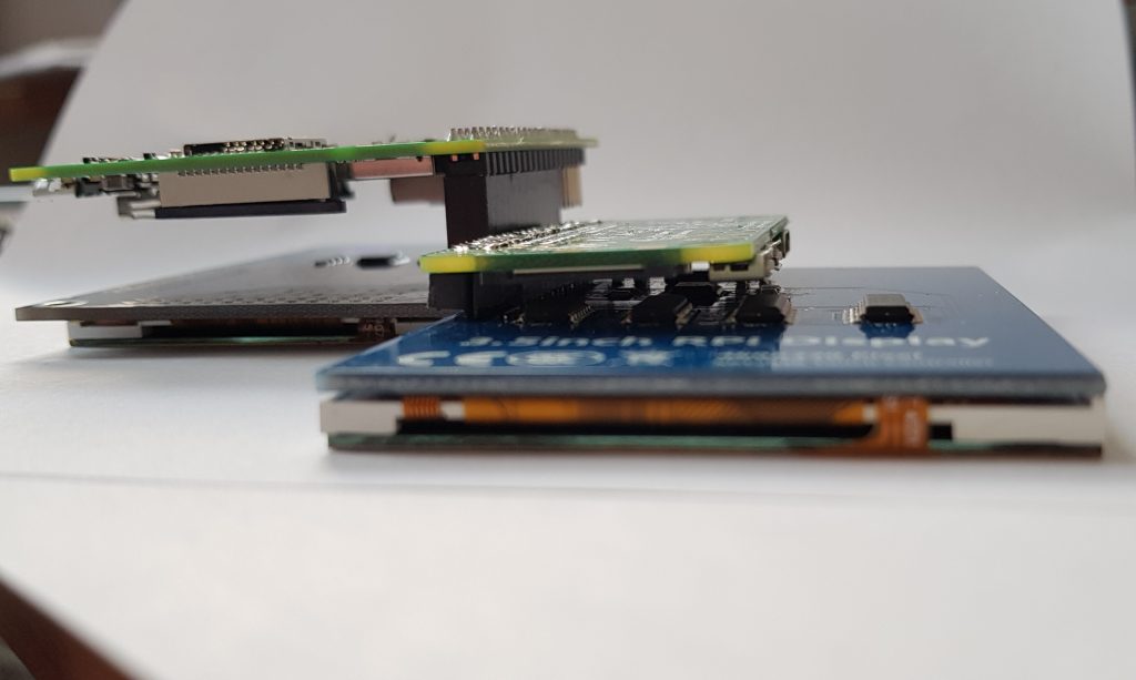
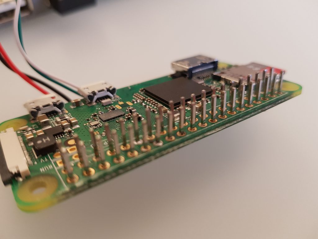
Another thing was to ideally keep the height of the original keyboard which is about 12mm, but looking at the standard plugs of GPIO displays, it became clear that I need to apply some tricks:
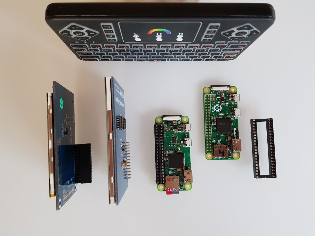
plug deprived display, pi with a plug
I soldered the rails of a DIP plug to the pi, took away the whole plug from the display cutting off the pins to a bare minimum.
great height reduction.
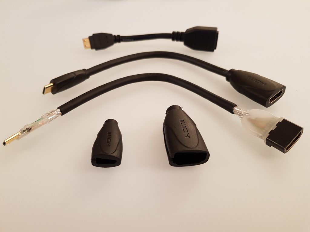
I also decided that I wanted to have a full size HDMI out so I bought shorter and more flexible cables than I had at home and dismantled them:
decomposing an HDMI cable reduces weight and increases flexibility.
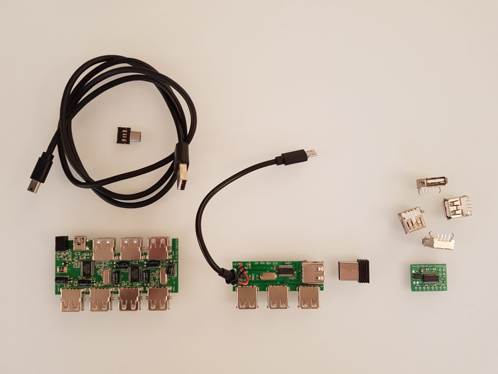
Finally, i also wanted to add a decent non-OTG USB to the machine as OTG adaptors simply SUCK.
Different USB hubs to select from.
I actually went with a little board that included the OTG “logic” already and had one USB on the side to actually keep the keyboard receiver and stay within the devices case.
before dcomposing the USB 4 port hub.
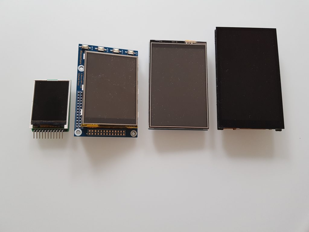
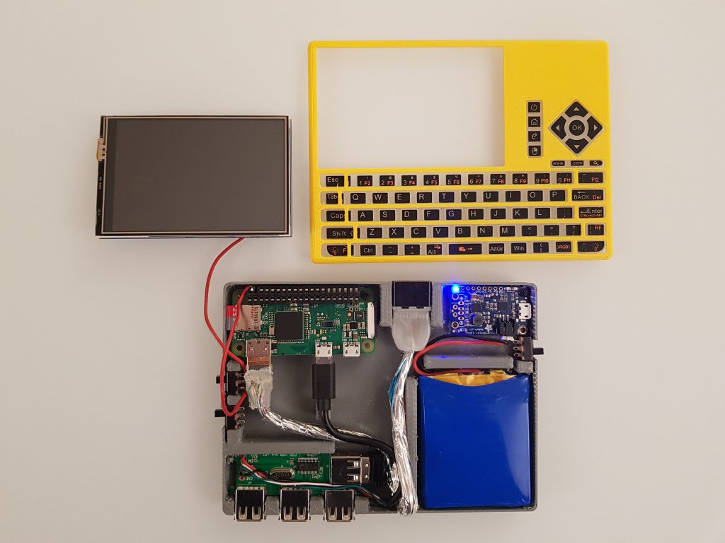
During the journey, I decided to upgrade to the final Hyperpixel 4 inch display, with a decent 800×480 resolution. The advantage is the little increased size (4mm) compared to my 3.5inch before plus it can be switched off via GPIO. So this is the evolution of the displays over the project:
1.8 inch, 2.8 inch, 3.5 inch, 4.0 inch
I also added the Adafruit Powerboost 1000 and a rather flat 3000mAh LiPo to the mix. The Adafruit is rather expensive (20-30€) and only supports 1A charging current, I’d love to have a cheaper charger board with 2A at some point in time.
With the power source in place, it was time to wire it all up. Note that I added another switch to the keyboard so that I could switch off the keyboard but let the Pi run for background computations.
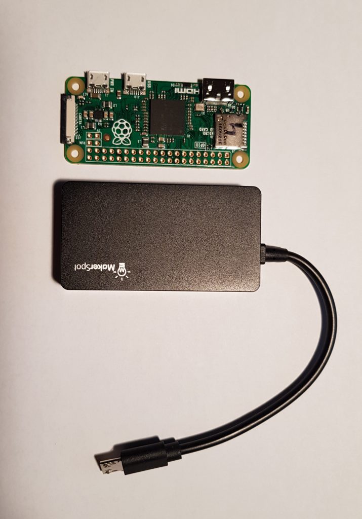
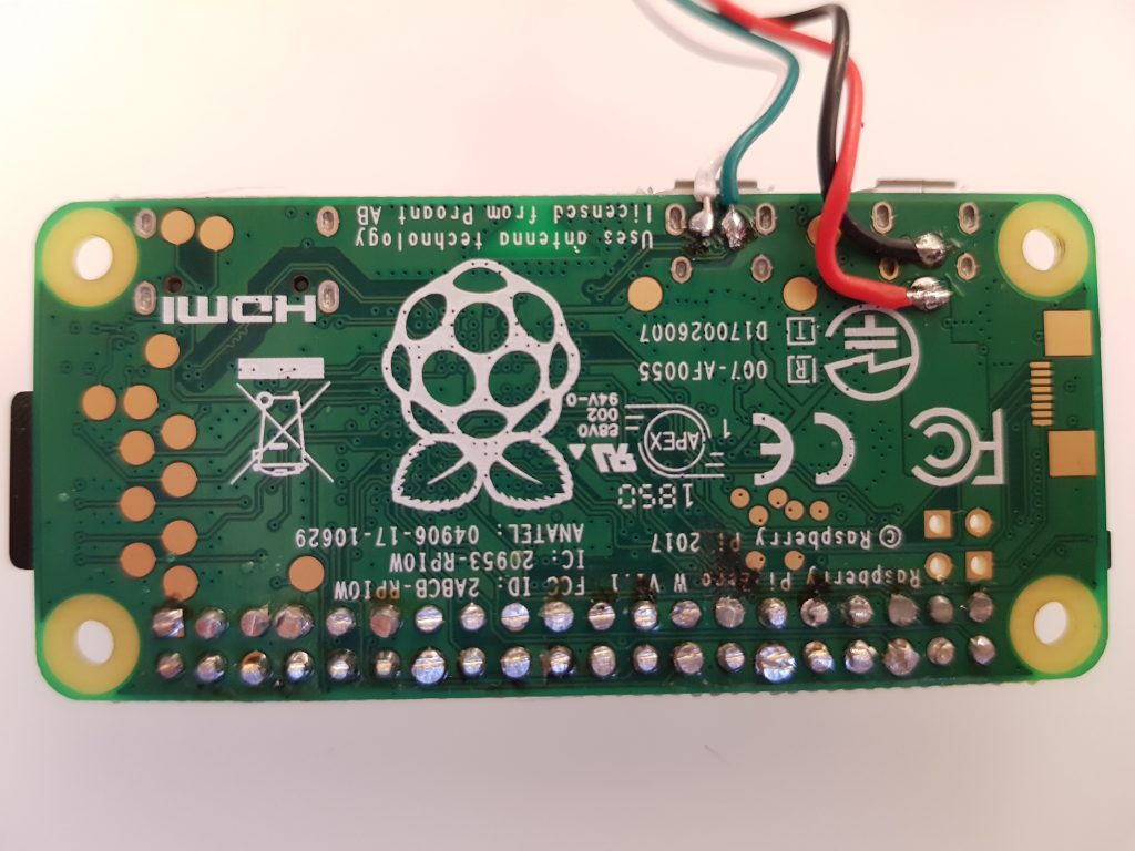
As you can see, I wired the USB hub directly to the Pi to save some more weight and space:
Wiring the OTG USB hub directly to the Pi.
Another trick to save height with also the new Hyperpixel display (the plug of the screen is okay, so I needed a new Pi Zero without the DIPs and just short pins), is to solder the pins with the plastic spacer from behind and then remove it plus the excess pin lengths on the back:
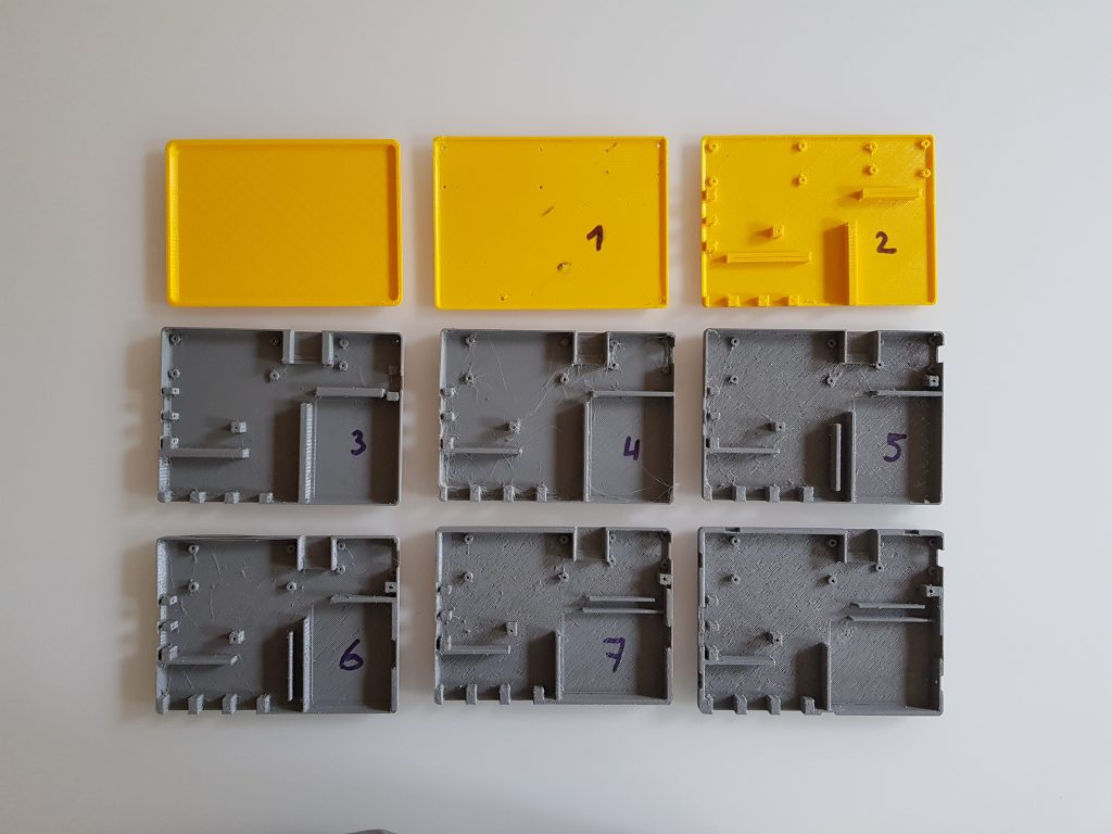
After the system was established, it was time to design the case and get a feeling for the locations of everything:
[earlier version with the 7 port USB hub and 3.5inch screen.][earlier version with the 3.5 inch screen and first attempt to make the display switchable.]
A later version then had spacing elements between the components to hold them in place. Also the HDMI output cable was added then:
As mentioned before, the screen switch for the 3.5 inch didn’t work as you could switch it off (cutting off 5V with the physical switch) but not on again since the OS wouldn’t re-recognise the screen then.
So the whole case design (TinkerCad) underwent a couple iterations:
As you can see in iterations 7 & 8, the battery was rotated 90° to landscape and the HDMI cable is going between battery and battery charger.
During these iterations the device grew a bit in dimensions to a final 11x14cm. That’s 3cm more than the original keyboard’s case at 8x14cm. But anyway that’s the price for a 4inch screen with a 800×480 resolution…
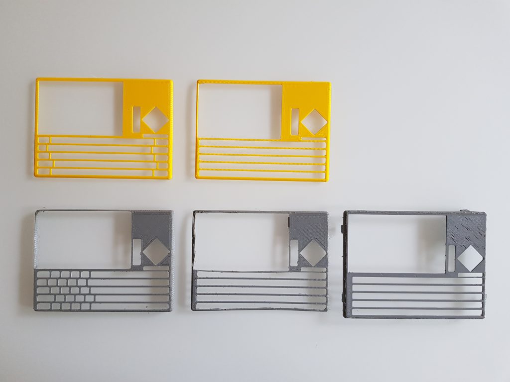
designing the holes for the keys is a pain in the butt…
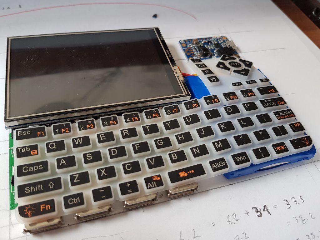
So that’s the currently final layout:
Time to look at the functionality in a video:
FIRST BOOT UP!
As I wanted to take the PocketPi to my easter holidays, I needed trade the flat screw “lips” to be bold and rounded to give the hole thing more stability:
bold screw holders, not nice, but survived the holidays / travel.
I installed Raspbian Stretch lite and added the Pixel desktop plus Geany as python IDE. I also configured two of the buttons to zoom the text in Geany, the right mouse key on the keyboard is really handy, the touch screen works as left mouse button and I added multiple desktops to easily switch between apps. Here’s a video of the currently final device in operation:
/i/49335/products/2019-02-27T20%3A54%3A20.119Z-20190227_215059.jpg?1606306133)