The next important thing was to give the robot more personality and I found one or two chaps in the internet that worked on LED matrix eyes. But I also wanted to get computer vision to Omnibot so that it could see things or people and potentially speak to them, grab them or move towards them.
So let’s start with the decomposition of the original eyes which basically had a little lamp build in:
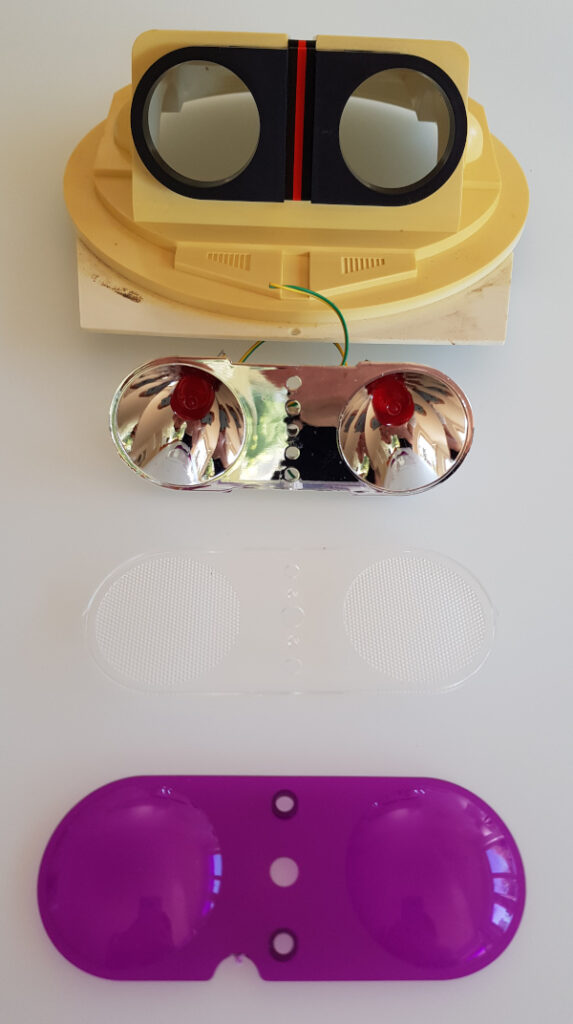
I decided to just keep the head plate and the black adapter and replace all other parts. Next I soldered the two 8×8 LED matrices, they are chainable and adapted the code from the above link.
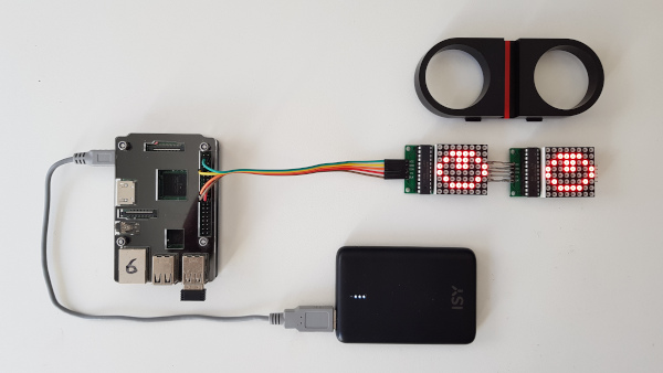
This was very satisfying as there was a quick success. However, as you can see, the MAX7219 controller chip is standing out of the black adapter, making it impossible to build the eyes into the adapter. So the next iteration was to desolder them again and rotate them 90 degrees…
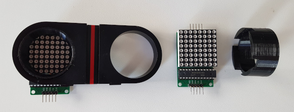
I also decided to design a 3d printed adapter to keep the squared matrix in the round hole.
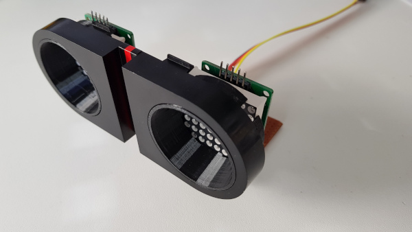
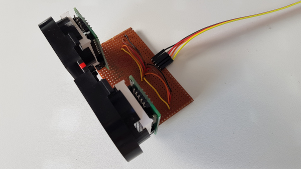
I also had to connect the two LED matrices differently as the pins would look downwards now. I decided to use a perf-board that I had in my cupboard from since my teenage years, so it would match the Omnibot in age 😀
A little software experiment yielded this:
When I was working on the Omnibot’s eyes, the high resolution Raspberry Pi cameras were launched and I had to buy them immediately. I don’t really like the flimsy design on the original Pi cams.
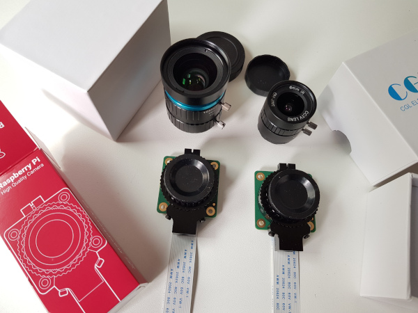
I decided to use the fish eye lens as it is small enough and would broaden the Field of View of the Omnibot.
I realised that the original black Omnibot adapter certainly has no hole for the objective, but I definetly wanted to have the camera very close to the LED eyes. So I decided to do away with the adapter altogether and re-designed the whole adapter to keep the objective as well. This was not too easy as the diameter is really huge and I wanted to keep the matrices at a maximum in size.
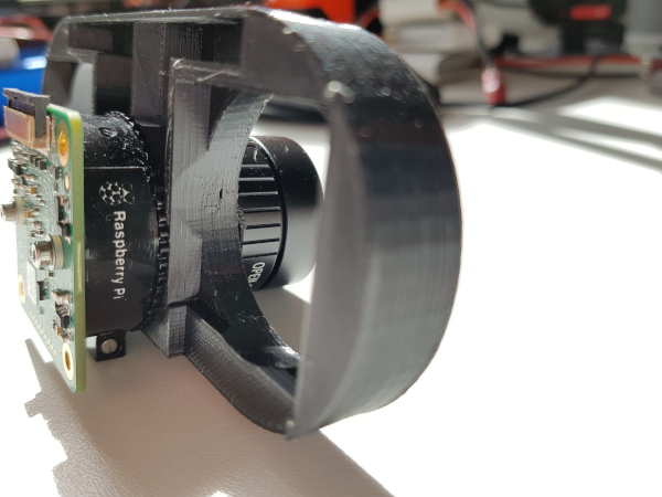
Finally, I also had to match the PCB with the matrix PCBs which also was not too easy. But luckily, it worked out:
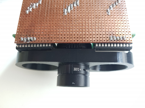
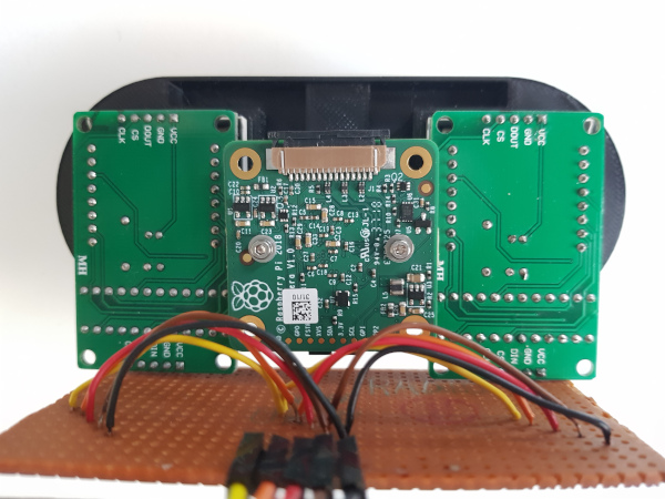
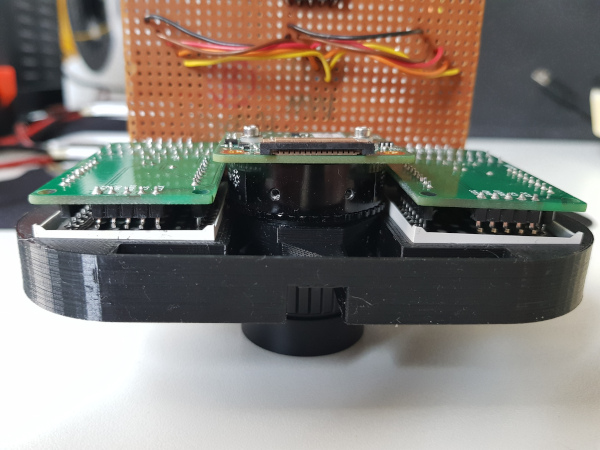
Finally, I had to buy a longer cable to connect the camera to the Raspberry Pi that was mounted on the Omnibot 5402’s tape recorder base plate in the meantime.
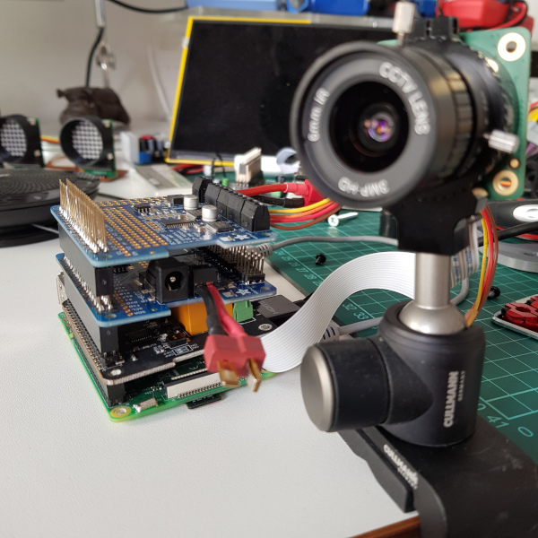
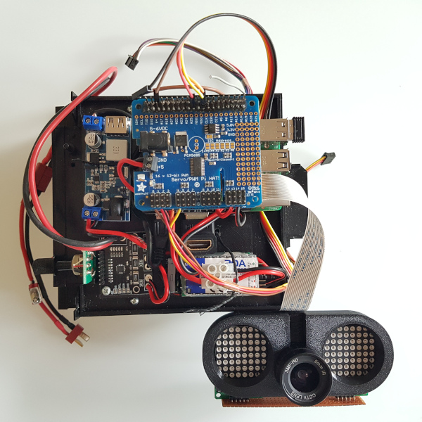
So, finally, all pieces come together in under the dome of the head part. The dome is dimming the picture a bit, so experiments will show whether computer vision works well enough. The manual focus of the Pi cam is helping here.
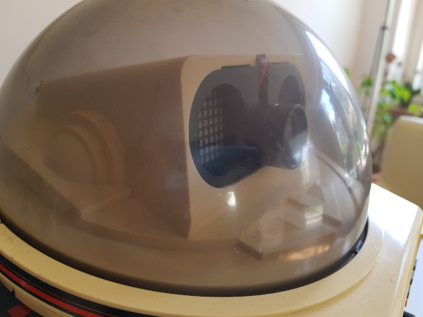
See the currently final setup here:

