Category Archives: trashbot

trashbot 3: a gimbal-like autonomous 2DOF spine

(if you can’t wait to see the end result, scroll down to the bottom watch the second last video 😉 )

after the lower body was walking and free from seizures when starting up the arduino, it was time to think about the rest of the robot. certainly, there’s still much to improve on the gait and most importantly the feet, but it’s my goal to build up the complete robot first before iterating the parts (the feet are under constant change as the weight distribution varies and also i’m constantly learning how to improve gait pattern.)

in contrast to many commercially available robots (like the bioloid or the lynxmotion pete), i wanted to have a machine that feels more natural and can move a bit more freely, especially with the head and the body trunk. usually, these two are rather stiff or absent (head). people invest dozens of servos into legs but not a single one into the spine. for me, the two servo legs are “good enough” for the moment, i’ll invest in the rest first.

on the other hand i’ve seen many gimbal mechanics mostly for quadcopters carrying the camera. some of them were even arduino controlled and here and there, you can see some code. interestingly, i wasn’t really able to find servo-driven automatic gimbals, most of those are driven by dc motors.

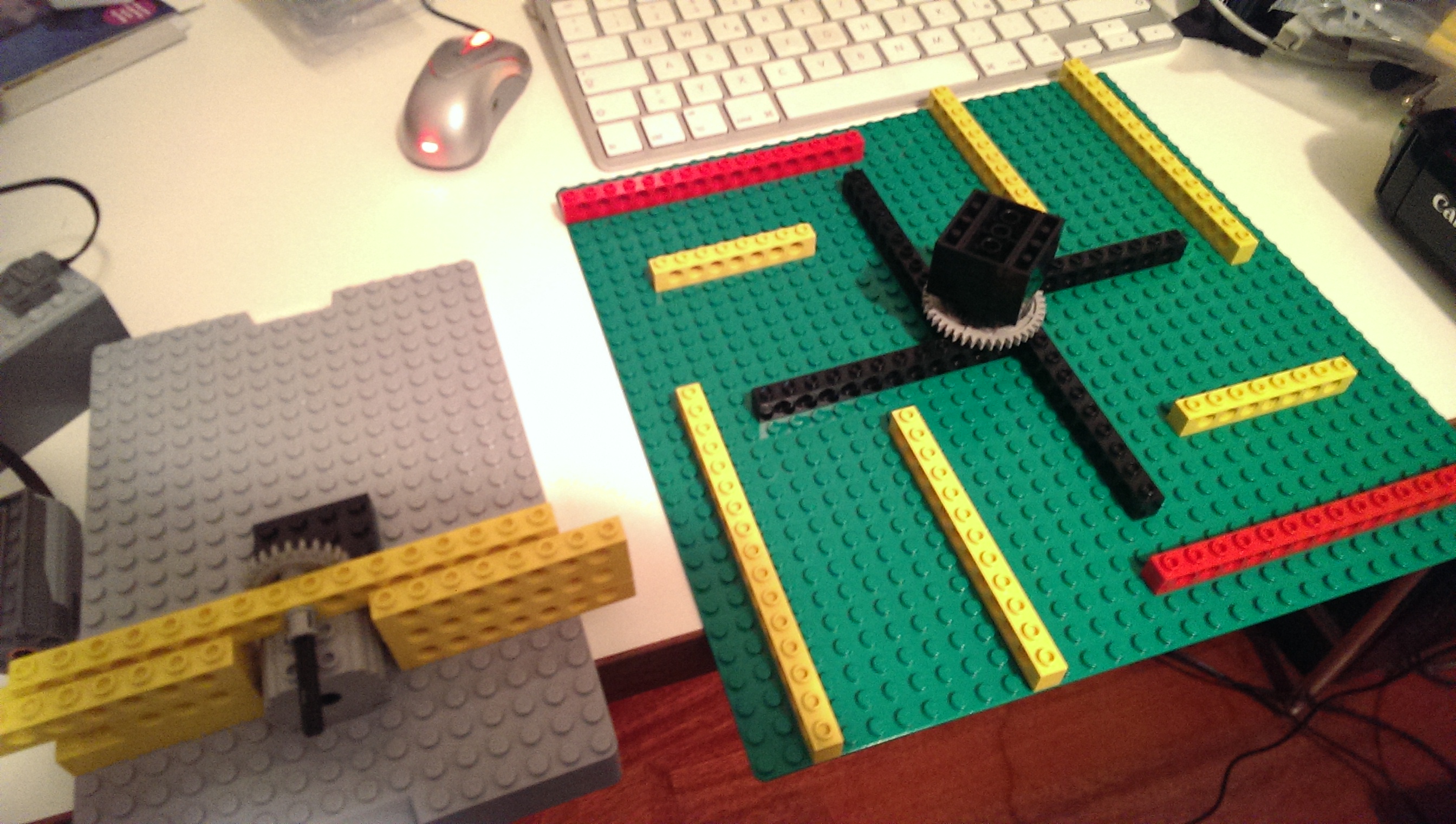
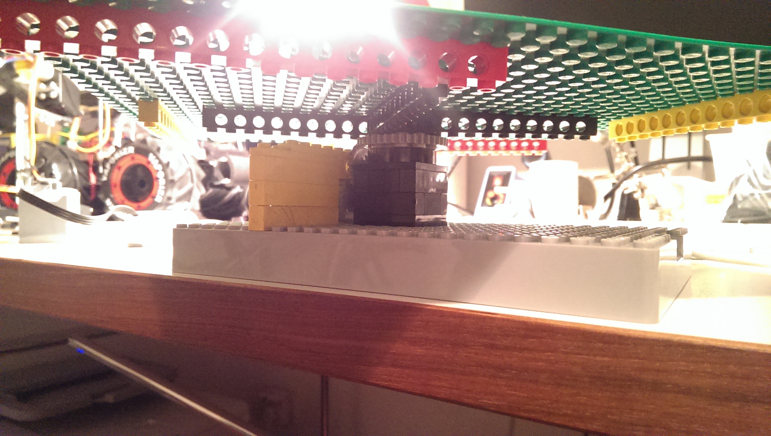
let’s view the goal first:

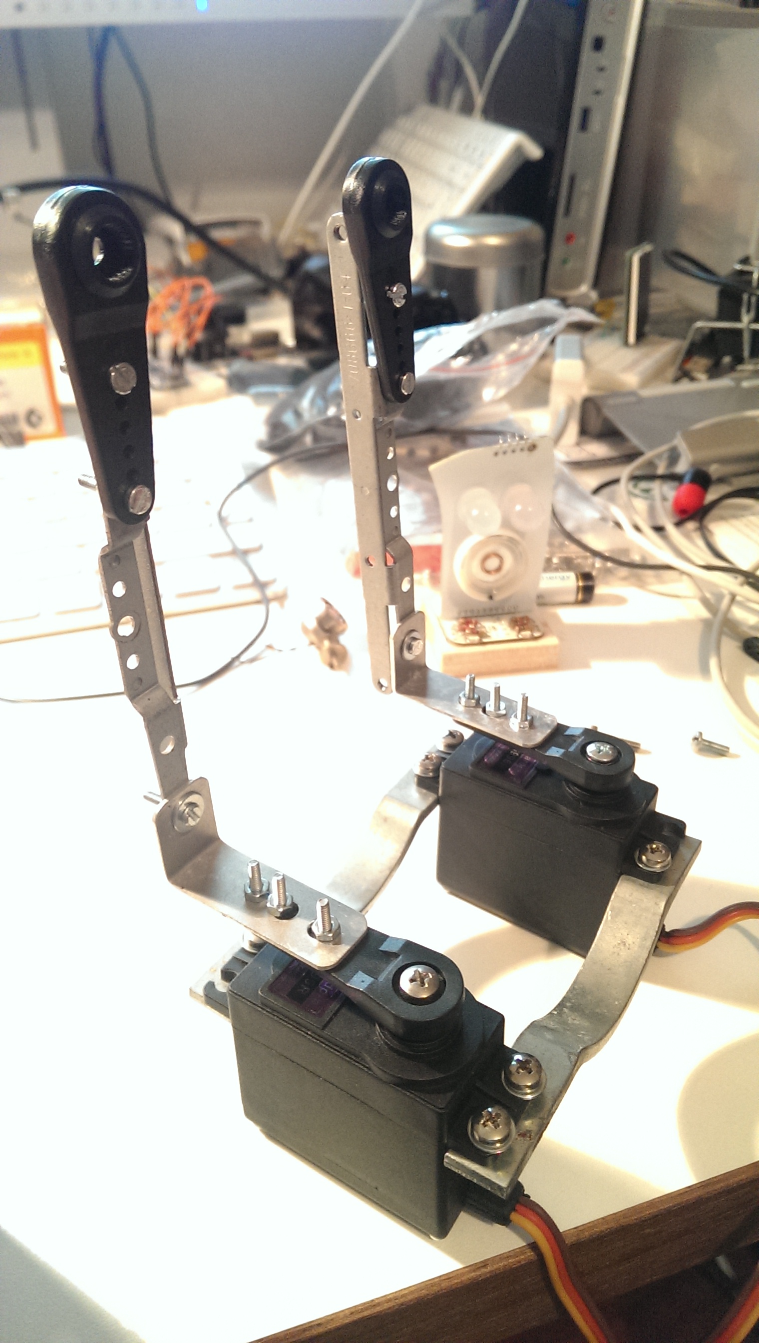
okay, here’s how i built it:

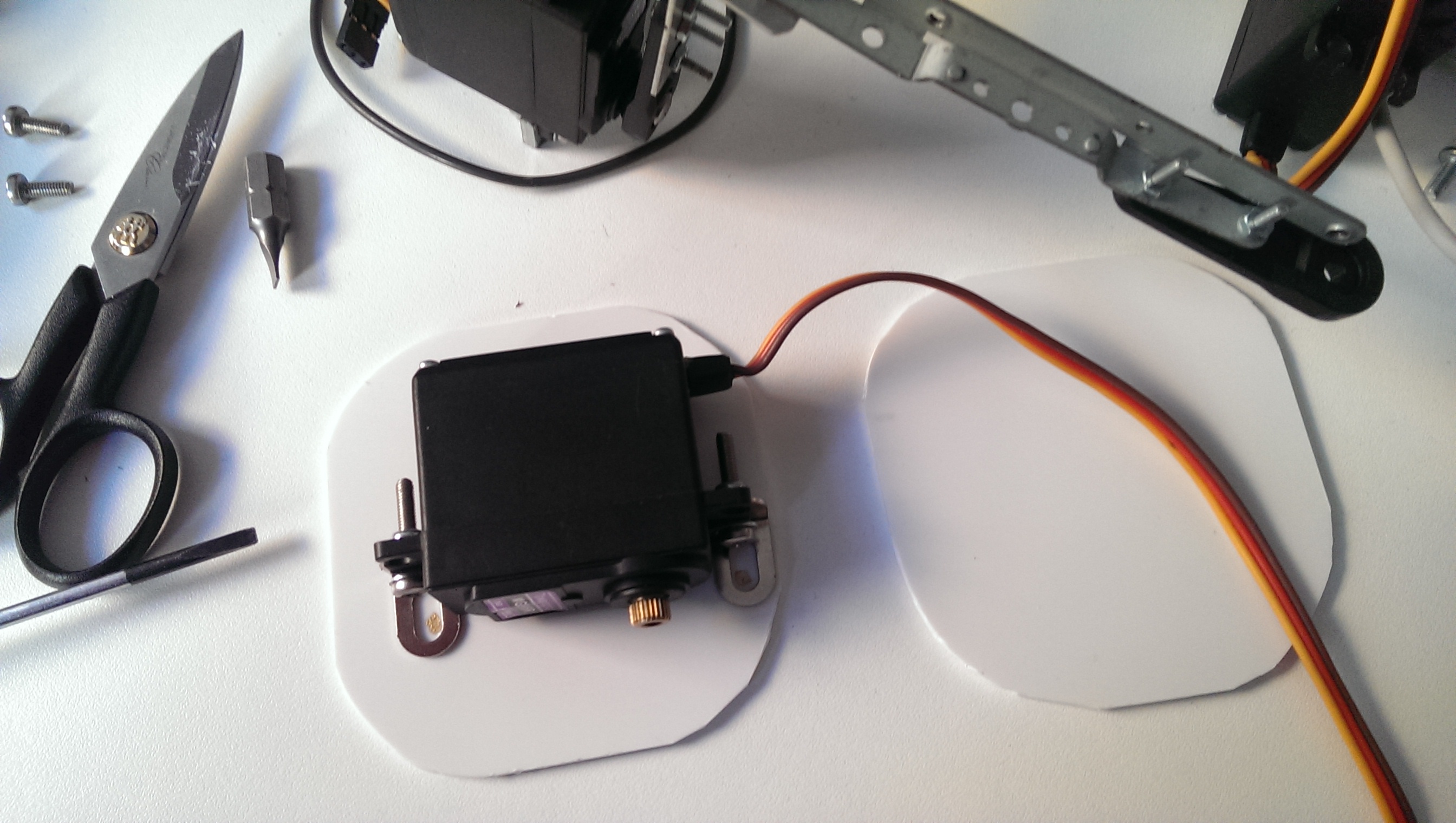
the base was taken from anold bike light:

bike light

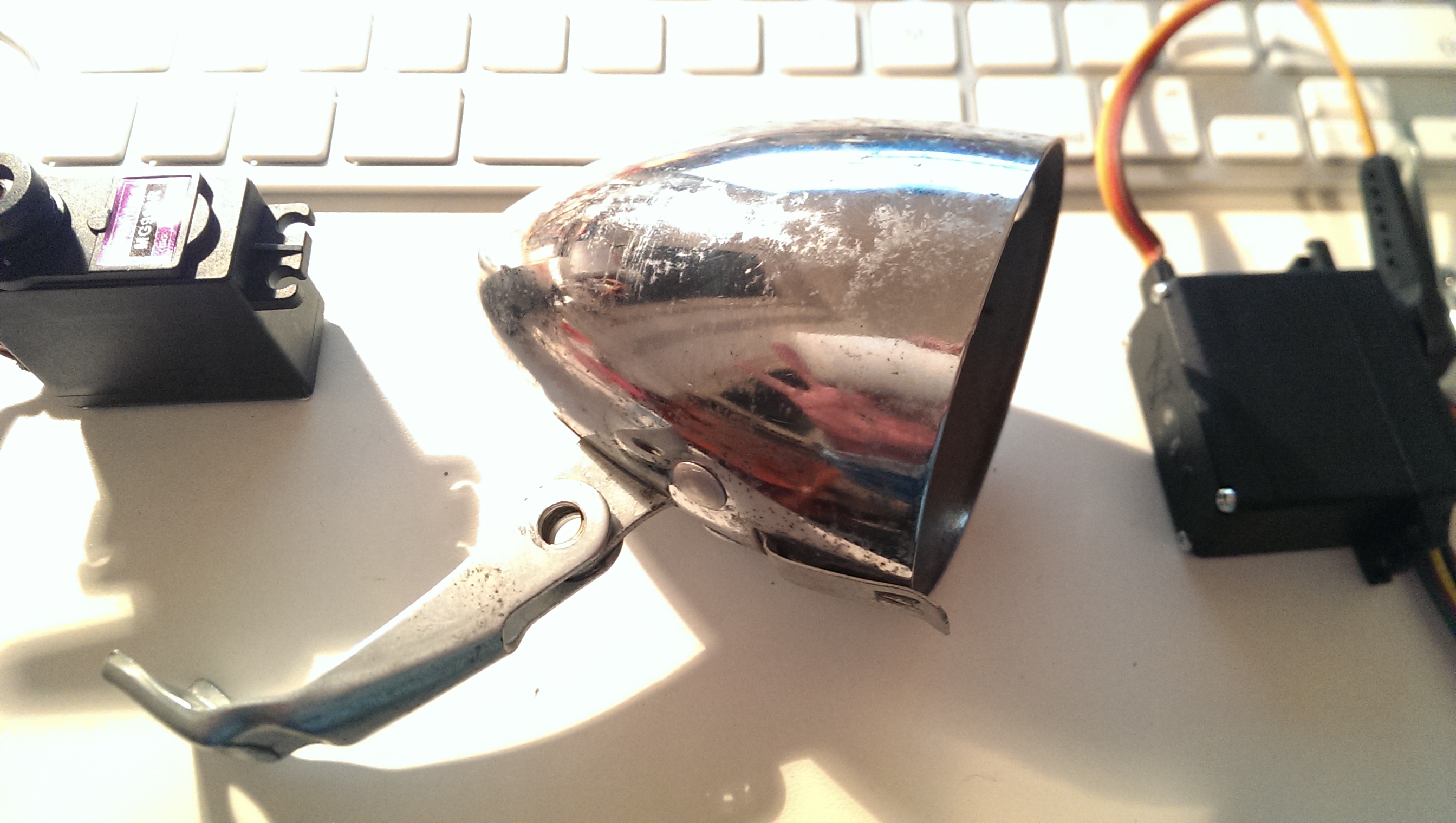
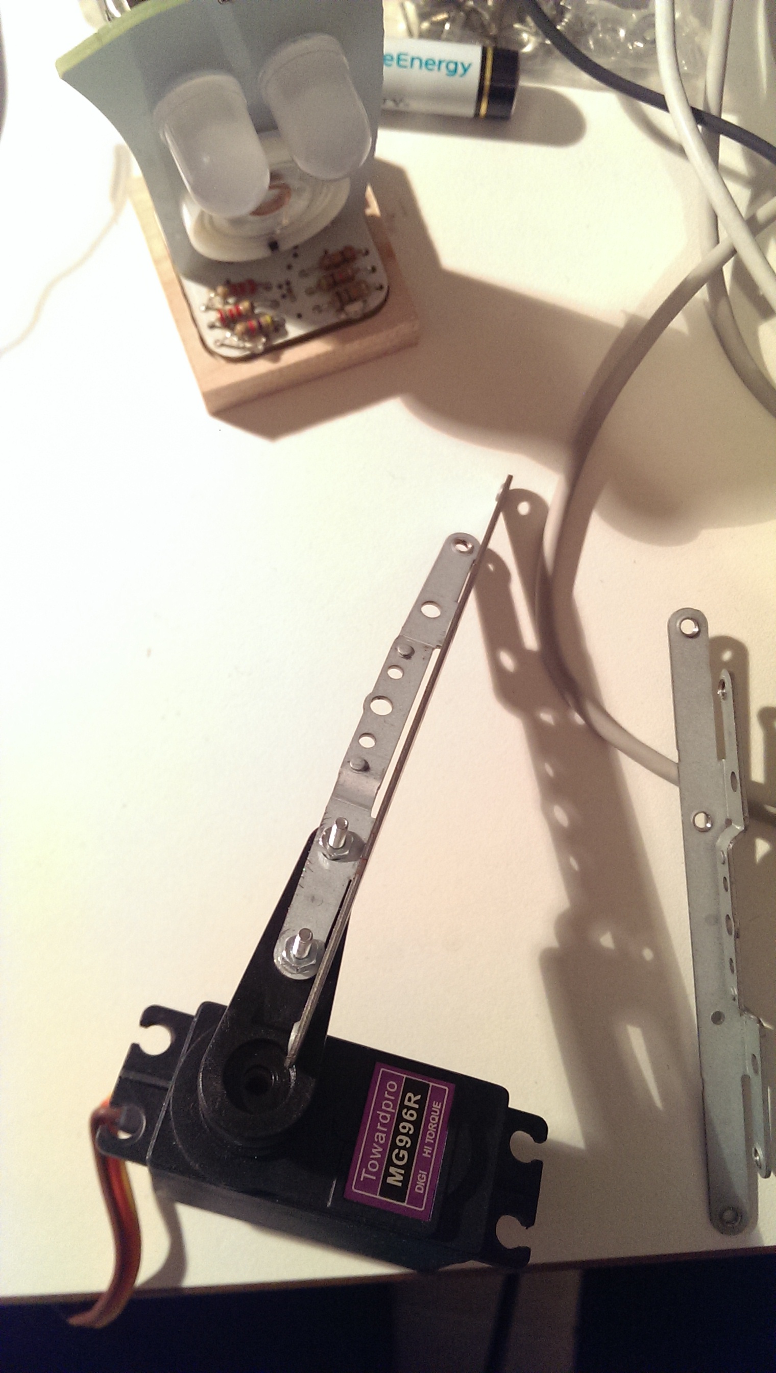
and i added the first servo that can swing from left to right:

lower servo for the back

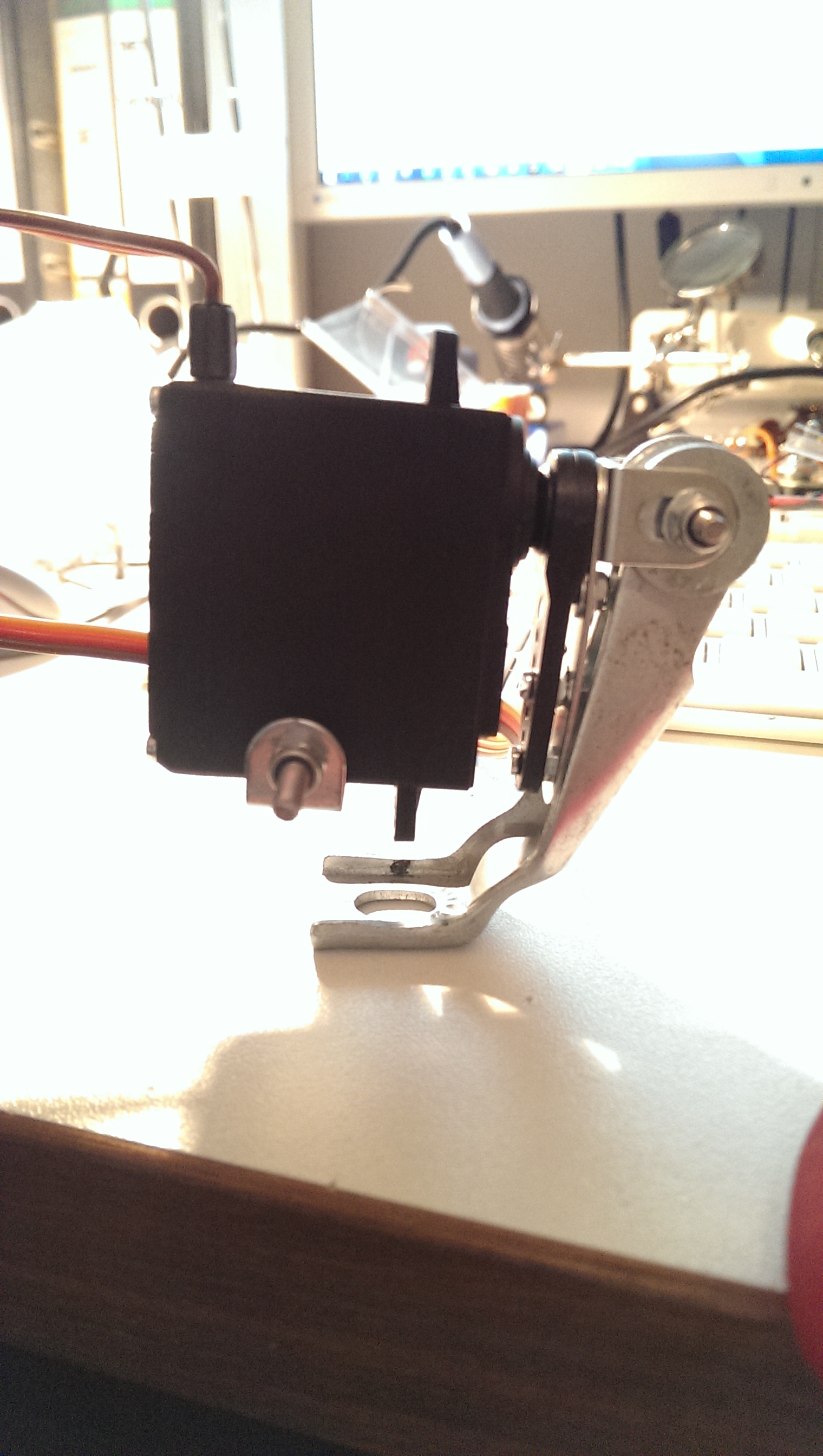
next up, was the second servo driving the chest allowing the bot to lean forward. it seemed to me that these are the two directions the biped needs to be stabilised in, since the feed generate a tilt to the sides and the hips rotate body on that tilted axis.

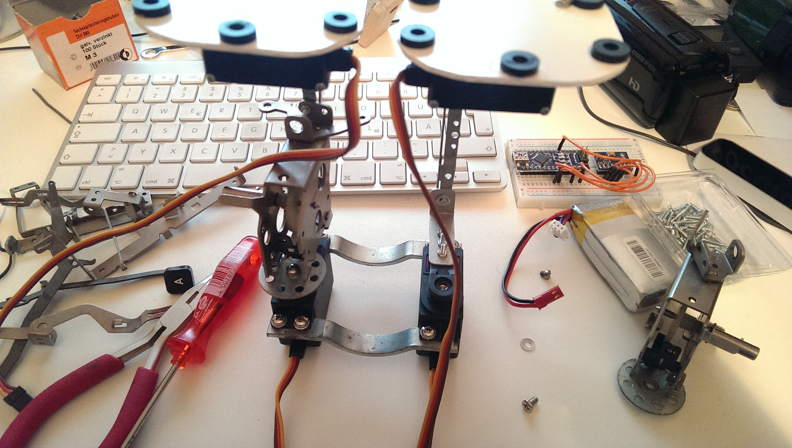
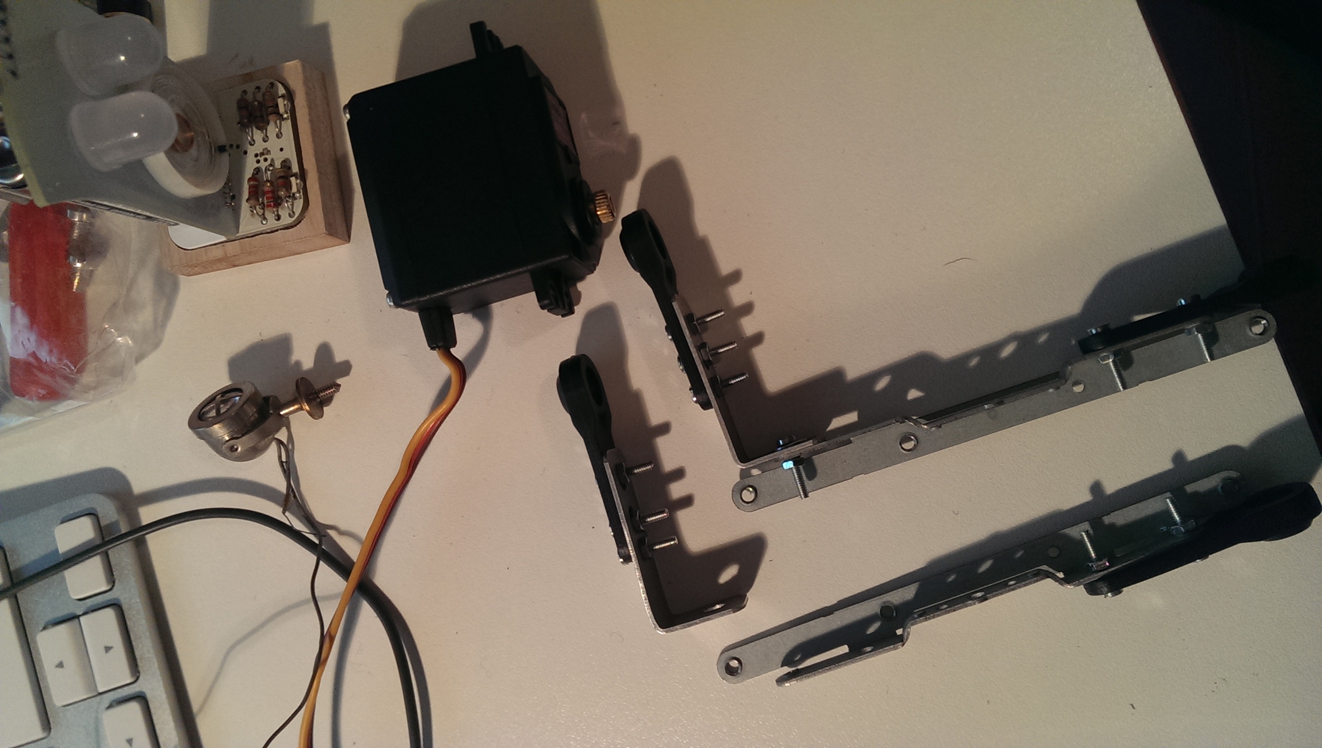
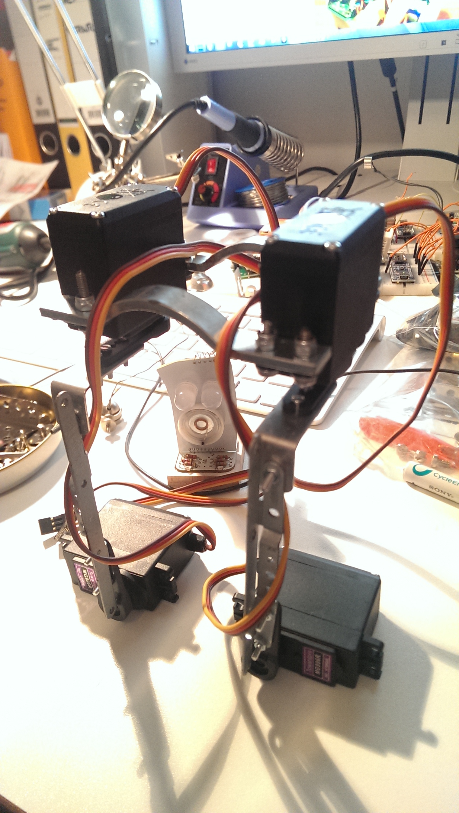
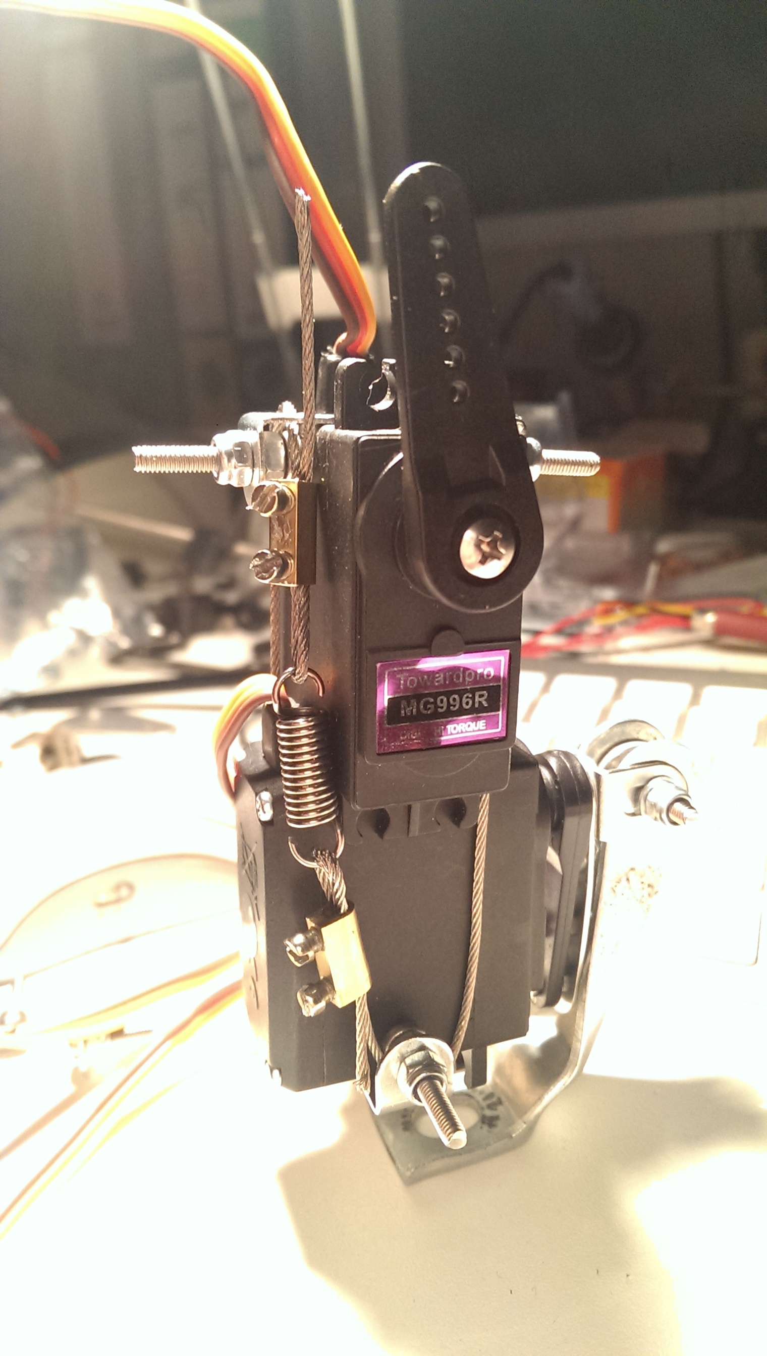
i wanted to have a possibility to update the mechanism easily and didn’t want to glue or solder anything, also bulky servo brackets seemed not the right way to go aesthetically. so i came up with a wire-based connection of the two made from a recycled wire that i had left from hanging lamps and some power connectors and a spring from the recycled typewriter:

connecting chest and back servo

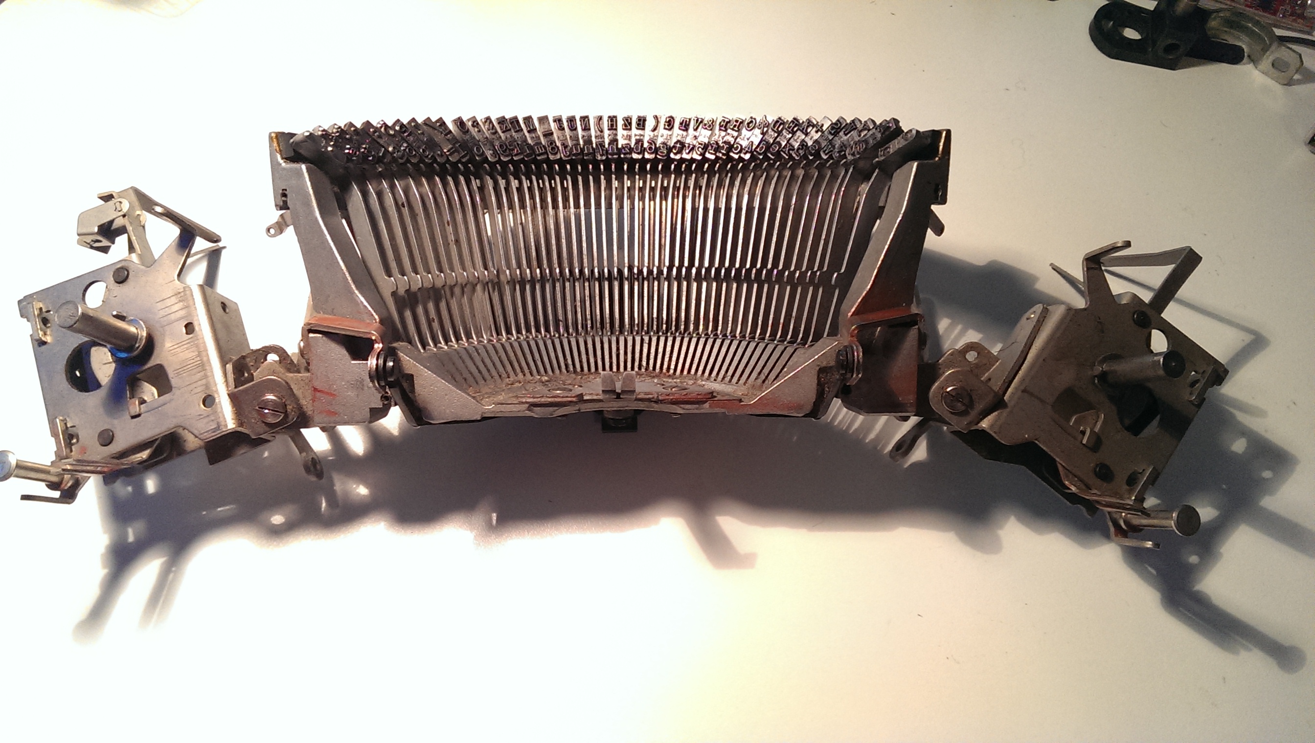
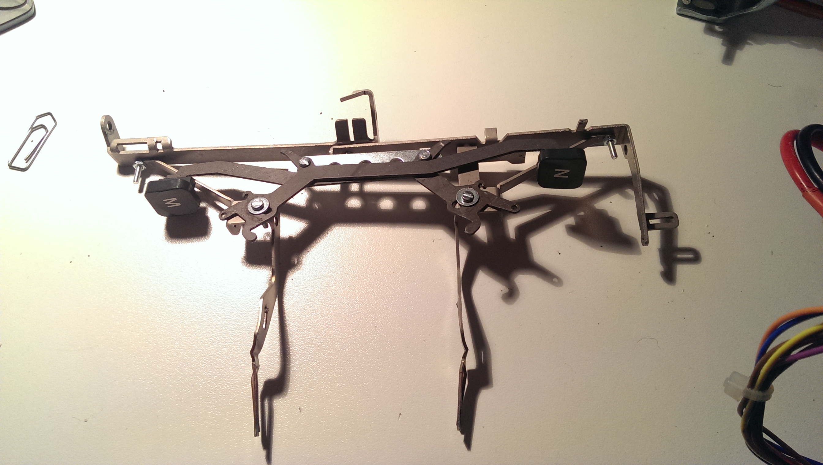
it took a while to find the right parts from the type writer and re-arrange them so that i had a broad enough shoulder that could work as a “servo bracket” while being stable enough to support more hardware on top later on.  and i recycled my first two letters “M” and “N”:

chest and should bracket

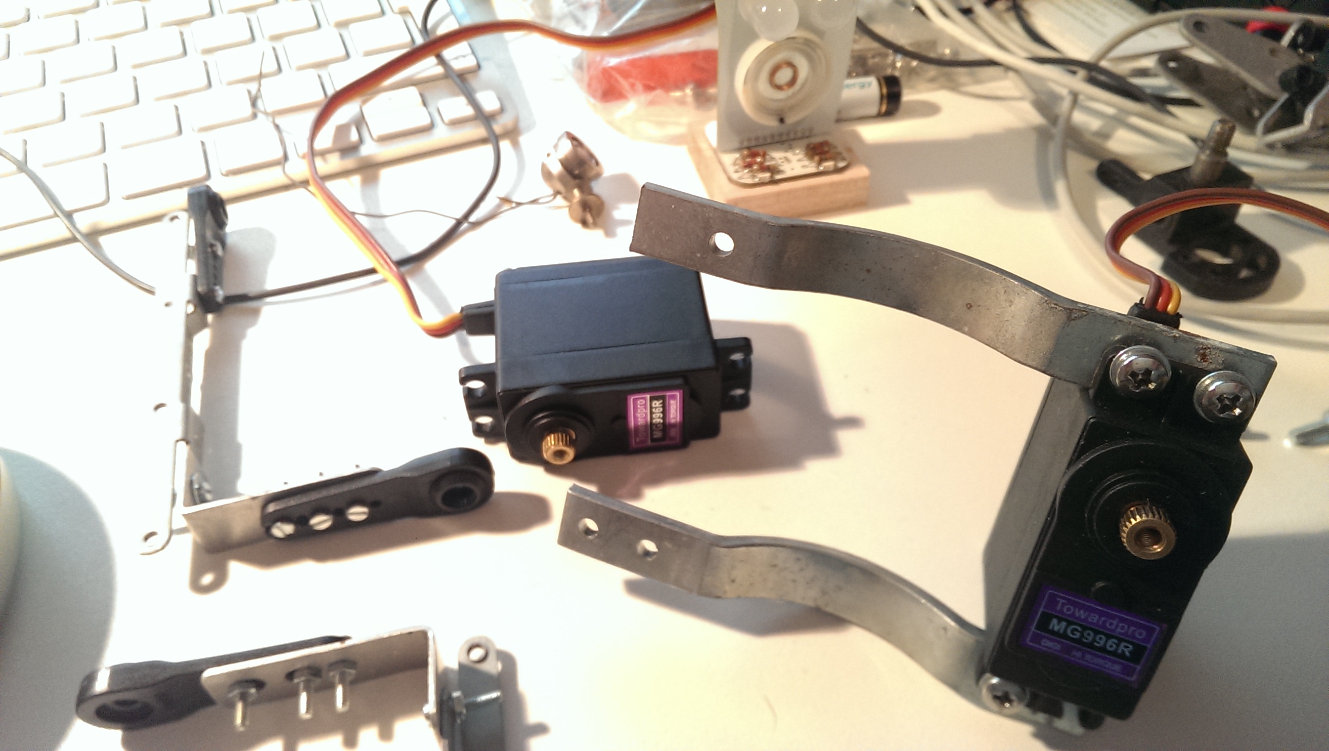
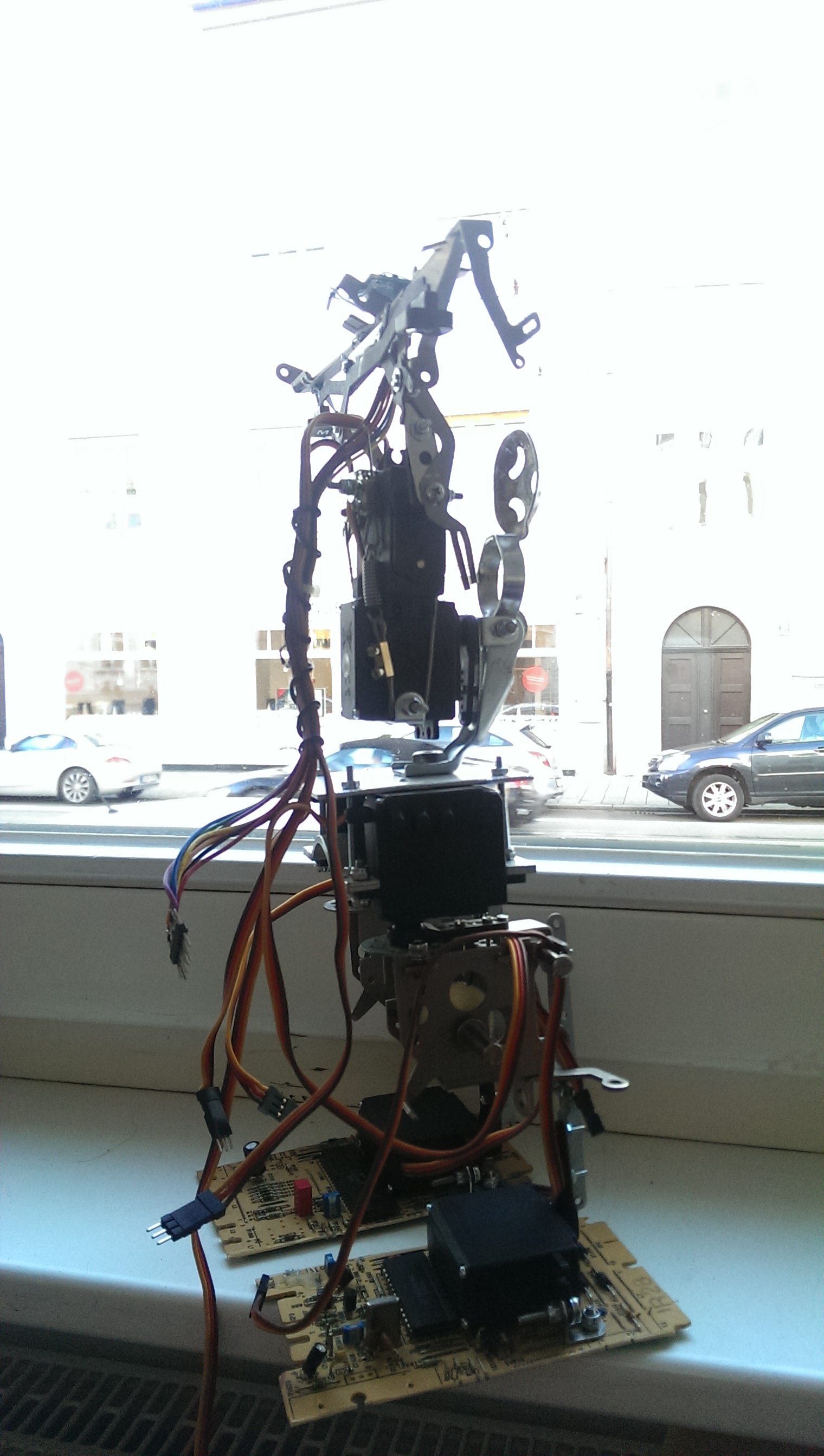
finally, connecting the two parts to this:

upper body assembled

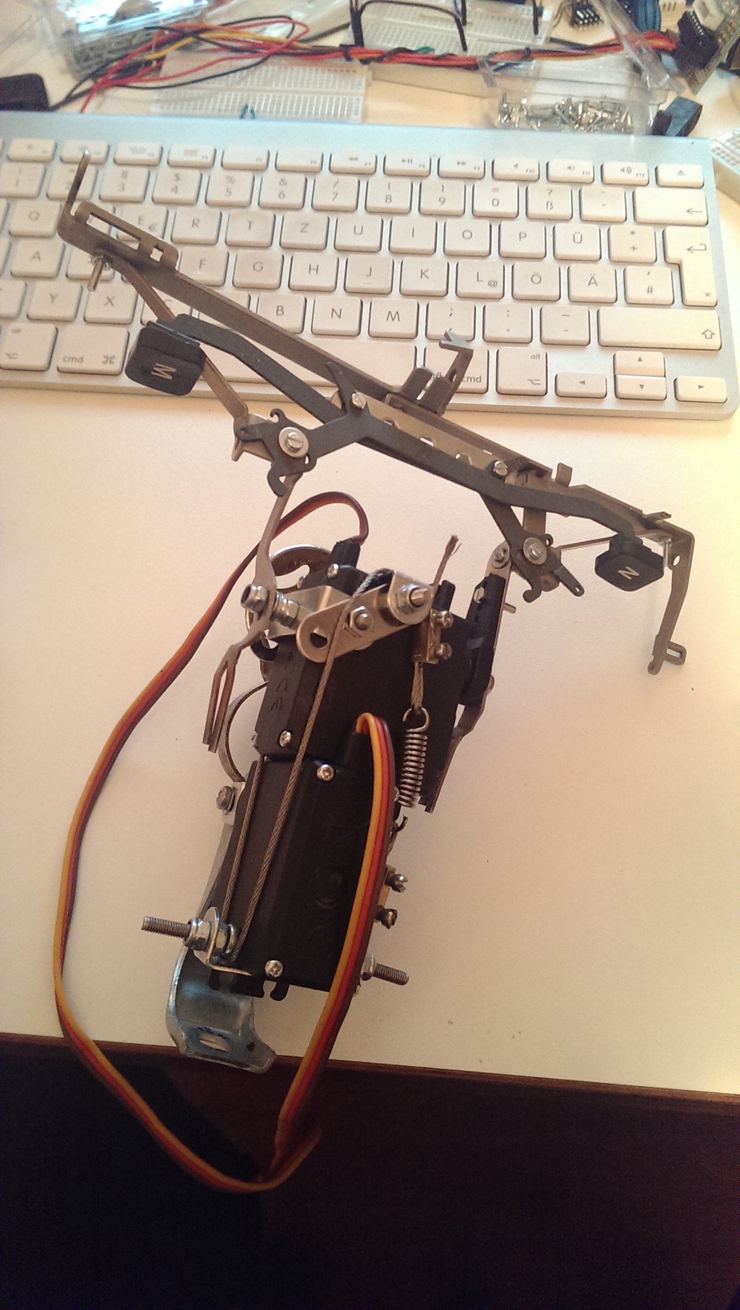
it was really tricky to find some parts to surround the upper servo so that i could atttach a second ankle on the other side of the servo. kind of proud to have it included in the wire fixation structure… also, you see a recycled air pump holder from an old bike that protects the bot’s chest servo should it fall backwards.

next i recycled a heat pipe from an old (TV?) pcb: heat pipe

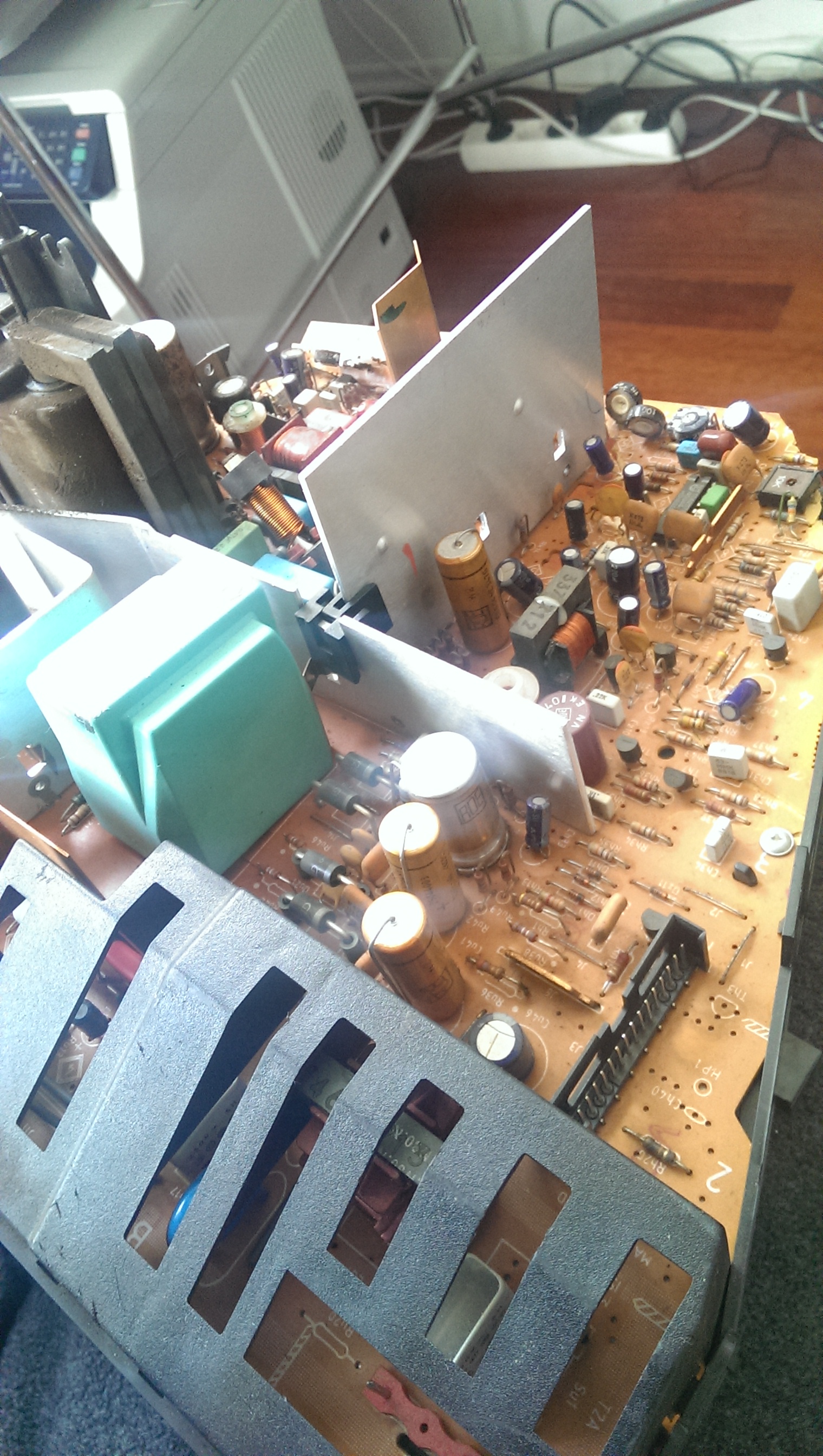
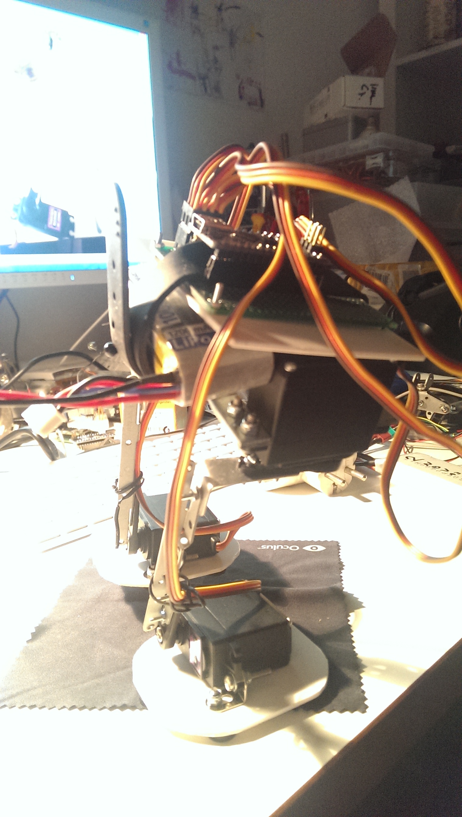
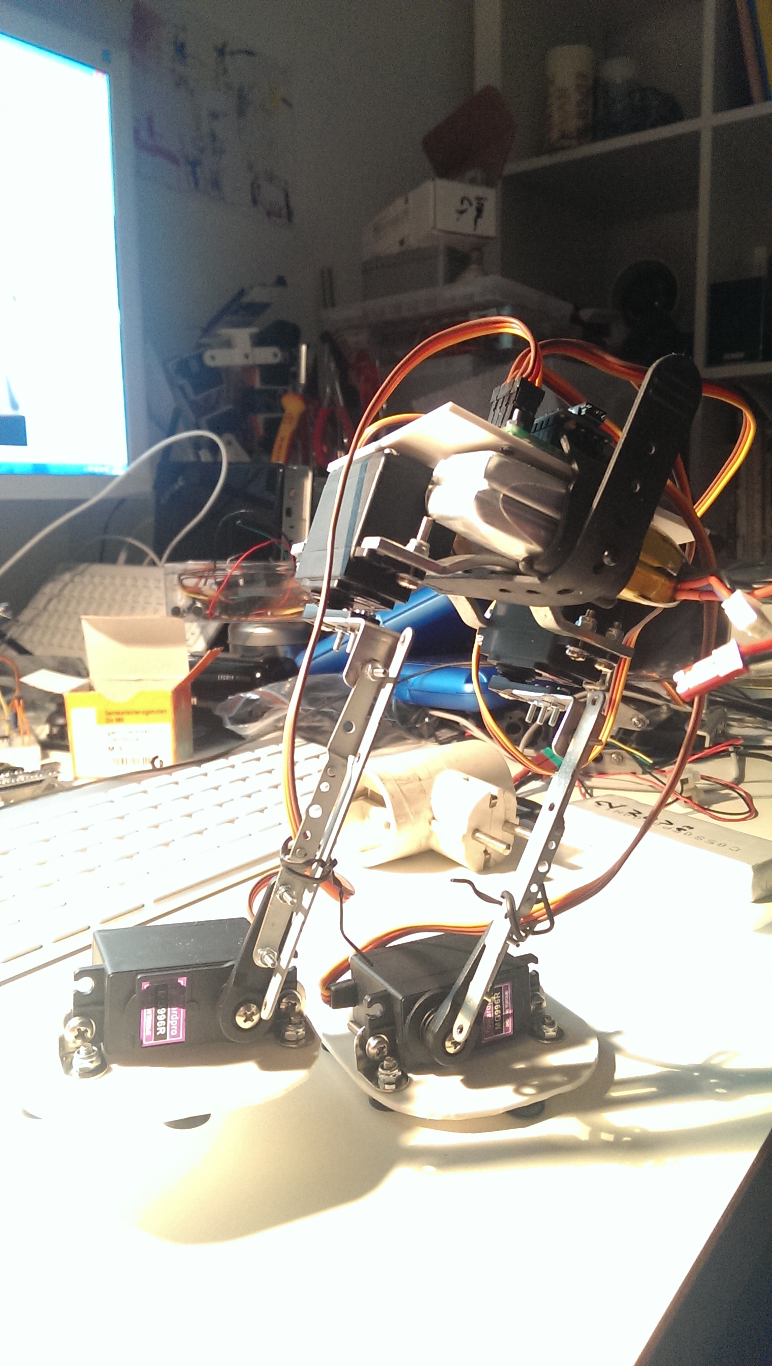
and shaped it to support the upper body on top of the hips and TADAA! here’s the assembled trashbot 3: trashbot v3 mechanics front

trashbot v3 assembled mechanics side

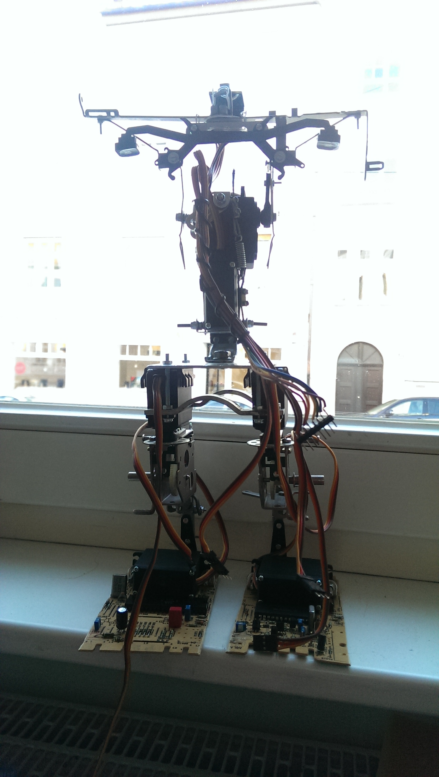
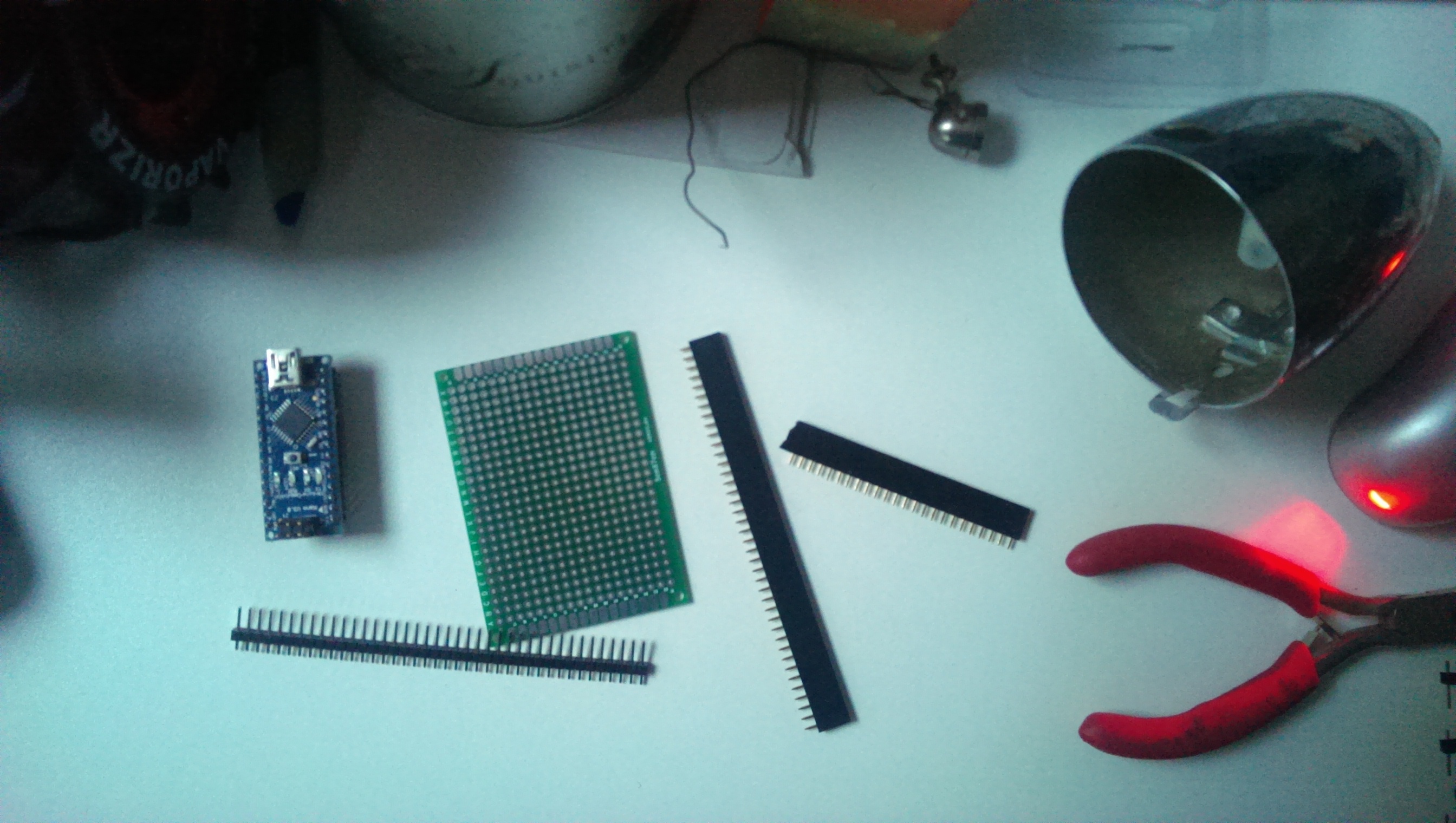
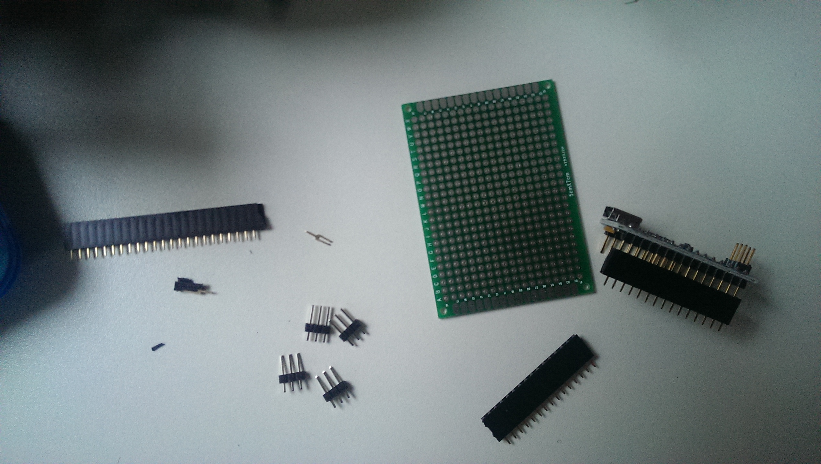
now it was time to develop the electronics and the software. (actually, i developed the software with the spine detached and assembled the whole beast when the autonomous gimbal was actually working).

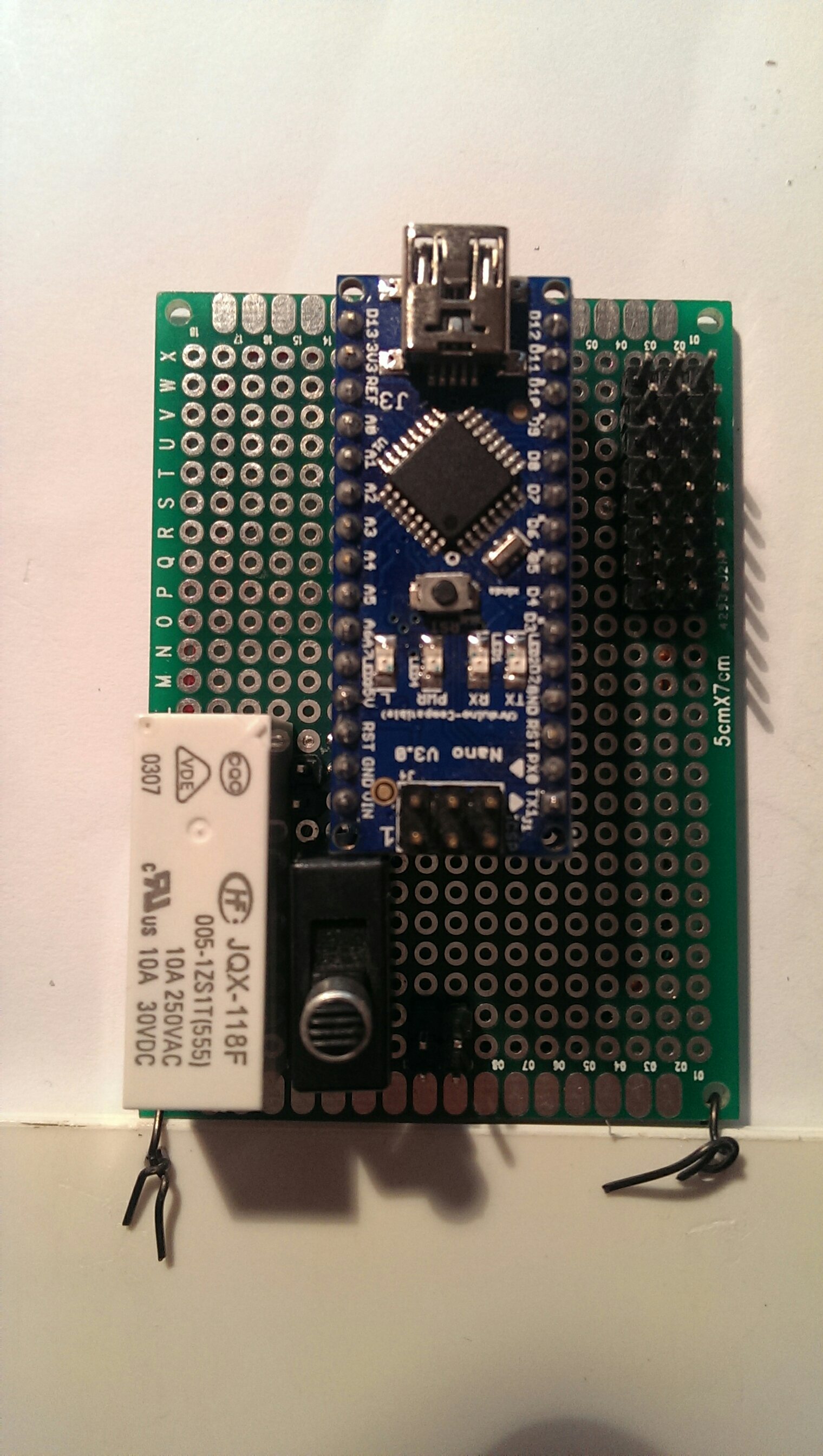
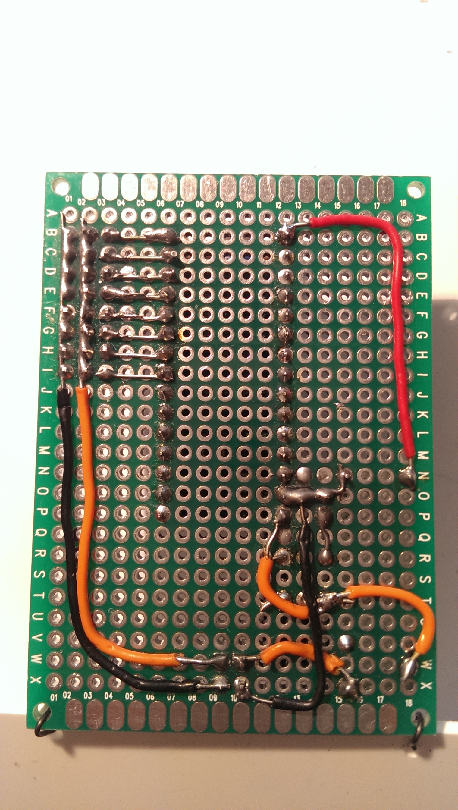
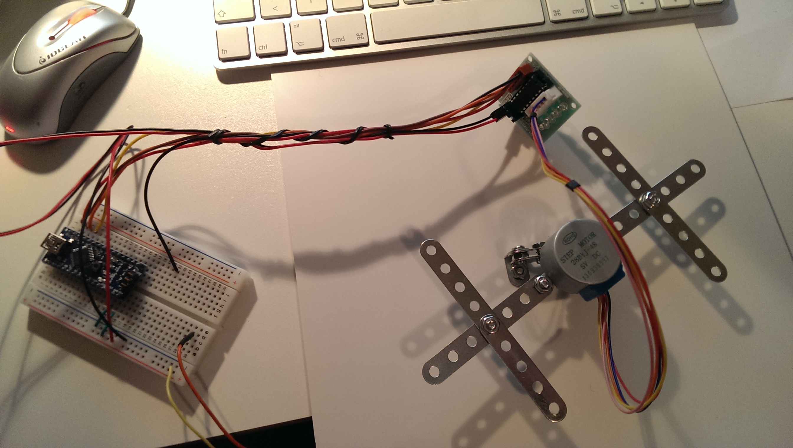
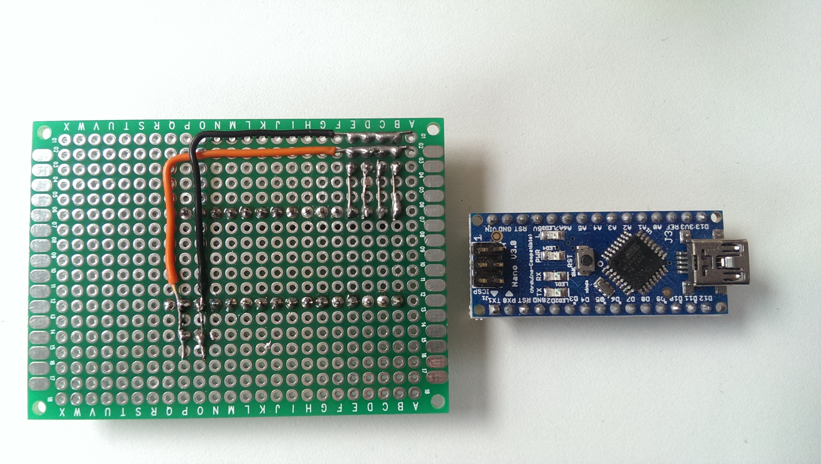
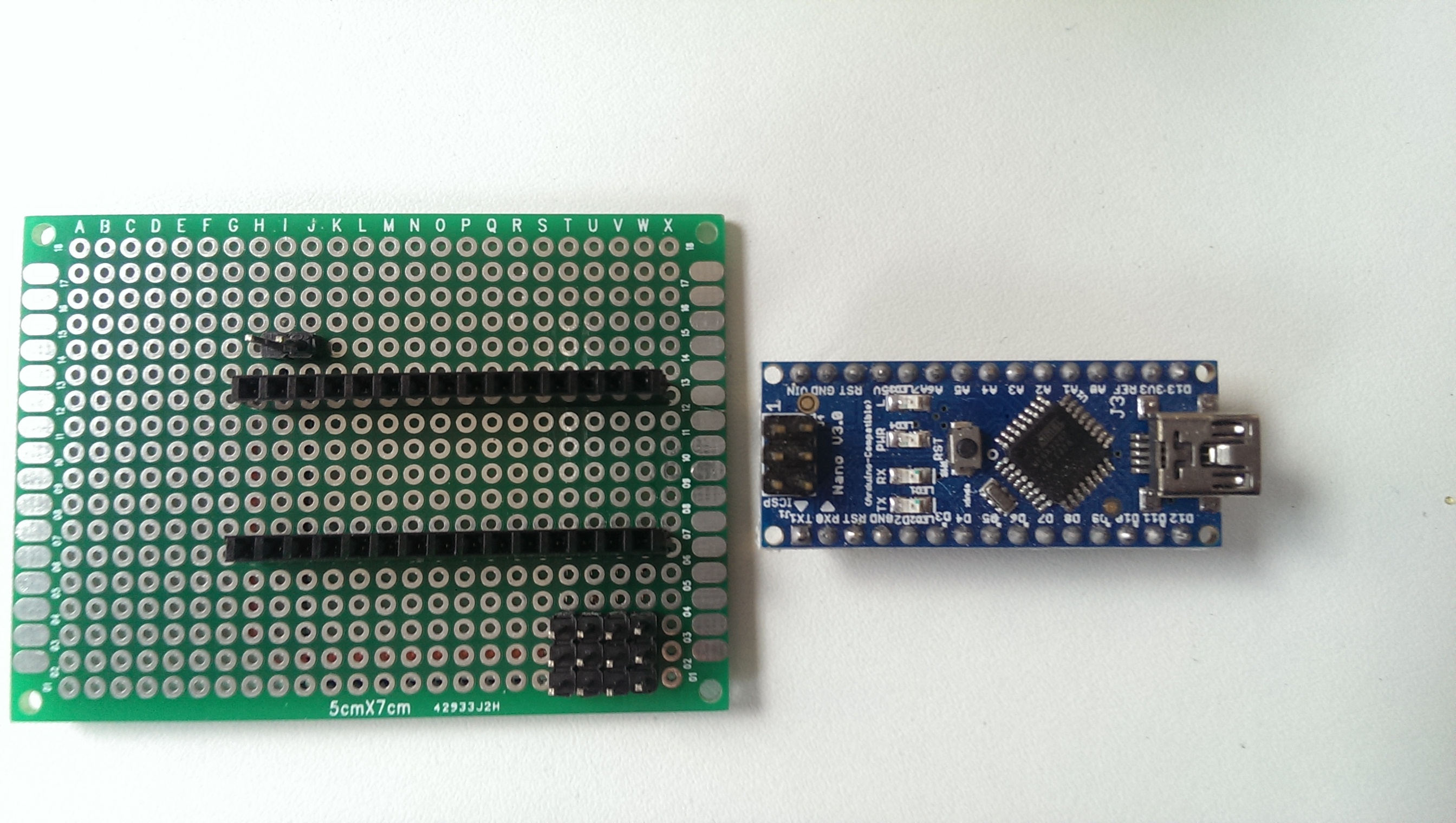
standard setup with the gyro / accel MPU6050, most importantly with the interrupt attached to the arduino:

MPU6050


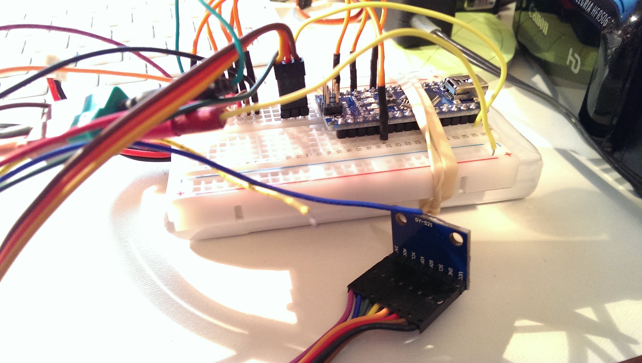
i tried a could of libraries for getting decent values (including the kalman filtering that can be done on the DSP of the MPU itself), but jeff rowberg’s is simply the best.

finally i wrote my own PID functions, mostly to understand how the maths work and how and whether i can fine tune something. PIDs are beasts as they are designed to self balance to a set value. now if the actuator and the sensor are attached to each other and controlled via a PID the whole system can swing like HELL. actually i burnt my first servo playing with the setup and was happy to learn that my humble mechanic design worked really well for maintainability…

i used mostly these links to understand how it works:

and lots of reading around this. the problem is that nobody can tell you how to tune your PID in your setup. so there’s a whole lot of trial and error with many strategies being published on how to find the right parameters. as you can see in the video, the parameters are sort of okay, but still the system is behaving a bit “choppy”. but if i react too often to the sensor values, the system starts to swing. so here’s some homework left and i hope that this blog post will spur some discussion in the forums. and there’s a nice blog post that obviously led to the PID library included in the arduino software distribution. i also want to learn from that.

let’s see the system in action:

finally, i also studied a bit how the bot walks with and without the gimbal active. the first part of the video shows it from front and top with the gimbal active, the second part shows it from top and side with a stiff upper body.

you can see that the upper body’s lateral amplitude is higher when switched off. this will be even more the case when we load the shoulders with a head and arms in the next iterations.

i will do another blog post investigating the gimbal effect more deeply. i just bough a tiny camera that i can attach to the neck and will tape trashbot from “first person perspective” 🙂


trashbot version 2

it took a while to improve trashbot v1 to v2 (for the video, scroll down) as i had to do a couple of things first:

finally, i got decided to increase the trash share of the bot and get rid of the shiny new feet made from polystyrene and replace them with old PCBs. i also increased the length of the feet for better stability.

IMAG0859then cut out the feet:

IMAG0861

also added the typewriter’s “shift” mechanics:

IMAG0836

to the tighs as their angles were the major source of instability and shakiness:

IMAG0858

i also improved the electronics after my recent experiments with relays:

IMAG0866

from the top it looks like i just added the switch and the relay, but i also added more “ports” for four more servos (intended for the upper body) as well as a “port” next to the switch for an UBEC. see the real wiring here:

IMAG0868

as you can see the servos (left up) get their power via the “port” for the UBEC (bottom) and then via the switched part of the relay. the relay is powered directly by the arduino (red cable coming from top, arduino port d13).

the trick is that the relay is cuting off the servo power when not switched. the arduino then has to set d13 HIGH to power the relay’s coil and thus keep the power on. since the d13 can only be powered via software, the arduino can control the servos when it has booted up and during the boot up the servos don’t behave badly. (obviously the d13 could also be in a HIGH state when the arduino powers up but that seems to be just to short for the relay to react.)

alright, after all the construction mumbo jumbo, here’s the end result:

compare that to version 1:

i also used a new servo library VarSpeedServo which can move the servos at user defined speeds. not sure i’ll keep it because i want to experiment with more complext gait patterns but for now it’s a great solution.


3d scanning trashbot for later comparison

so, the last couple of days i invested more time into 3d scanning the first version of the trashbot before really going into improving it. turns out that scanning a 3d object using skanect is more complicated than i thought.

i’ll report three different methods here:

  1. build a rotating lego stand for the desktop
  2. walk around the object to scan
  3. build an arduino controlled stepper rotating stand

let’s see first what the scene to scan is:

1) i thought i build a little rotating stand using lego, so i stole some legos from my kids and build something like this:

lego stand decomposed

lego stand composed

next, i scanned it, letting the motor run and went into analysis:

2) next, i decided to actually put the robot on a stand that doesn’t move and move the camera around instead, also assuming that different heights may add information and get a more complete picture:

okay, cut the video to not bore you too much with it. i think the result is more interesting:

(yeah, that’s our garden plants in the background, we already had some snow in germany…)

finally, i found this skanect tutorial and thought, that obviously, the rotating stand is finally the way to go:

3) so i built  a little step-motor / arduino driven rotating stand so i could control the rotation speed (check out this blog entry on a MUCH better stepper library for arduino) much better than with the lego and isolated the object from nearby objects.

arduino stepper rotation

okay and here’s the result (sorry for the audio quality, don’t know what went wrong):

that’s currently my last attempt. i think for now, i got the best results by manually scanning the bot and not using the rotation / stepper.

TrashBot v1.0: my first four-servo biped robot that actually walks.

after the complicated start with ROFI, i decided to build my own biped from scratch but never really found the time and focus to do it. but then i came across “bob the biped” by bajdi over on letsmakerobots and i fell in love. immediately.

this guy has really done a great job designing a simple, working and cure biped that really is charming. the design principles fascinated my from the first second. he just used four servos, to on each side connected by an L upside down. the foot servo is used to shift the center of gravity, the hip servo is used to move to bot forward. the other side is working in a mirrored fashion, preparing the next move, so to speak.

also, the software is really nice as it produces the gait pattern parametrically and he also shared the source code. the gait pattern is actually one of the things that were too complicated with ROFI, esp since the original inventor’s design also included arduino, android and c# software.

so, okay, i decided to build my own interpretation of the core design of bob, of course i don’t have a 3d printer yet, but to me the casing is just icing on the cake, i need to understand the mechanics, gravity implications and dynamics of the gait.

here’s how i started, one foot servo (nice mg996r, metal gear machine) connected to a hard-drive holder from an old pc: feet and legs

next, i attached an L shaped metal piece i had floating around to the servo horn of the hip:

leg and knee

then, i found some metal pieces that had fortunately the holes drilled in the right distance to actually fit the servos’ holes:

metal hips


now i coulddo a test connection of legs and hips (in the end you have to decompose the ensemble again to center the servos before finalising the build up):

hip, servos and legs


now i could add the foot servos and voilá we have a standing prototype: standing prototype

of course the hard plastic of the feet is slippery, so i needed to add more “footage” as well as extend the standing area, so i cut out some feet from polystyrol which is hard enough to support stuff but soft enough to be cut with a knife (or actually sliced and then broken):rough cut outs of feet


cut out feet

and finally attached the feet servos to them with little screws and L shaped metals i had found:

IMAG0819


next, it was time to build some electronics. this time, i didn’t want to use the breadboard, i actually roughly know how the layout should look like so, i chose this time circuit boards and connector strips i had found at amazon: board and connectors


cut them into the right pieces to fit the arduino nano and four triple plugs of the servos plus some lipo connection:

cut connector strips


minimal circuit design (the nano can be powered by up to 12v, the lipo has 7.4, so i can power the servos and the nano with the same battery, i left out the bec for the moment):

circuit

as you can see the upper part gets power and gnd from the battery (on the lower part), that’s also powering vin and gnd of the arduino nano. here’s the front (top battery in, middle nano, lower right servos):

circuit front:


here’s the final bot from the side (some polystyrol to save the circuit from shorts by the metal hip) and the lipo attached to the front. as you can see, he can stand on one foot, which is the most important feature…

first key learning: long legs imply delicate balancing of the upper part. not very elegant. this is why the “bob” is so elegant, short legs, less risk to fall over… final bot side


here’s mr trashbot from the front (electronics and lipo attached with a rubberband, for fast component exchange and re-engineering. we’re learning!):

trashbot front view


finally, here’s the little guy walking. not too elegant as the long legs and the heavy metal gear servos make the legs shaking. and some software issues i guess (number of animation frames vs playback duration should be fine tuned, letting him walk faster will let the shakes become stronger in amplitude and let him fall more easily.)


i did a couple of tricks to the original source code. for example, i split the max angles the servos would do between hips and feet. this means that the feet can do larger angles than the hips. furthermore, i also gave the feet different max angles depending on whether they are up (less) or down (more). my feeling was that this way i would get the center of gravity close to the standing foot’s center.

but here’s really room for experimentation.

i think i’ll stiffen the legs next, possibly also add a gyro to the circuit and let the gait pattern adjust dynamically according to the shakes the hardware does so that he’ll move more slowly when the shakes become too strong. let’s see. finally, i may also add bluetooth for visualising the gyro’s recording to learn a bit more.

or add knee servos. in that way, the lifted leg could retract a bit which would pull the center of gravity a bit more inwards. but it would also add weight. hm… decisions, decisions. what would you suggest?